USC LPH800 Operator'S Manual Download Page 13

Page 13 

LPH800 TREATER 

Installation 

Section 

HIGH VOLTAGE ~ 

Always disconnect the power source       

before working on or near the control panel or lead wires.


HIGH VOLTAGE ~

 Use insulated tools when making             

adjustments while the controls are under power.  


Permanent installation may require additional electrical cords, 
chemical tubing, and air lines, since each installation is unique.
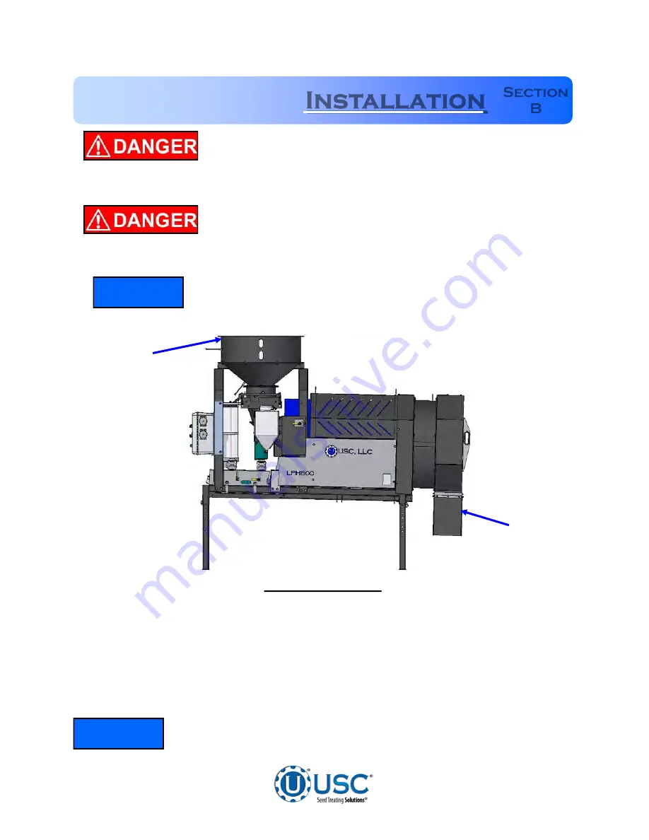
 

Rear 

Inlet 

Discharge 

Front 

TREATER SET 

-

 UP


The following steps outline the initial set

-

up of your USC Seed Treating system:


1.


Clear the area of bystanders, especially small children, before moving.


2.


Be sure there is enough clearance from overhead obstructions and power lines or 
other equipment to move the machine into its working position.


3.


Using a forklift, place the seed treater in the desired position on a level surface.  


USC highly recommends that the seed treater be set up inside a  
building or any covered structure to protect the machine from     
weathering.


NOTICE


NOTICE


Summary of Contents for LPH800

Page 1: ...Operators Manual LPH800 SEED TREATER 2320 124th Road Sabetha Kansas 66534 PH 785 431 7900 FAX 785 431 7950 www uscllc com Revision Effective 29 JULY 2015 Document TD 09 06 1033 Revision B ...

Page 2: ...hazards or special requirements arising from this specific application Allow only properly trained and instructed personnel to install operate or service this equipment Maintain a comprehensive safety program involving all who work with this machine and other associated process equipment Establish clear areas of staff responsibility e g operation setup sanitation maintenance and repairs Provide al...

Page 3: ...ffect your safety Failure to follow these instructions may result in serious personal injury or death RECEIVING YOUR EQUIPMENT As soon as the equipment is received it should be carefully inspected to make certain that it has sustained no damage during shipment and that all items listed on the packing list are accounted for If there is any damage or shortages the purchaser must immediately notify U...

Page 4: ...Liquid System Valves 22 Pump 2 Liquid System Valves 24 Section D Electrical Operation 26 Treater Control Panel 26 Section E Calibration 30 Seed Flow Calibration 30 Adjusting the Seed Flow Gate 31 Pump 1 Calibration 32 Pump 2 Calibration 34 Pump Charts 36 Treating Seed 38 Section F Troubleshooting 40 Proximity Switch Adjustment Guide 42 Section G Maintenance 43 Section H Storage 46 Section I Mechan...

Page 5: ...e small icons located in the left margin They indicate special information that may apply to your seed treater model As the legend below indicates there is 1 icon that represent a different seed treater setup If you have a Cotton Rice treater please take note when one of these pictures is shown because it provides pertinent information Legend ...

Page 6: ...meaning and format have been standardized for U S manufacturers and published by the American National Standards Institute ANSI The European Community E C has adopted a different format based on the International Standards Organization I S O and applicable machinery directives Both formats are presented below Graphic symbols are not standardized but most manufacturers will use some variation of th...

Page 7: ... Symbol This symbol indicates that an electrocution hazard exists Serious injury or death could result from contacting high voltage International Electrocution Hazard This symbol indicates that an electrocution hazard exists Serious injury or death could result from contacting high voltage Mandatory Read Manual Action Symbol I S O format This symbol instructs personnel to read the Operators Manual...

Page 8: ...o employees CONTROLLED STOP This is the stopping of machine motion by reducing the electrical command signal to 0 zero once the stop signal has been recognized The operator initiates this stop by pressing the PAUSE button at he bottom of the main screen HAZARD REVIEW Electrocution Hazard Electrocution accidents are most likely to occur during maintenance of the electrical system or when working on...

Page 9: ...instructions to operators or employees before allowing them to operate the machine and at least annually thereafter per OSHA Occupational Safety and Health Administration regulation 1928 57 The most important safety device on this equipment is a SAFE operator It is the operator s responsibility to read and understand ALL Safety and Operating instructions in the manual and to follow them All accide...

Page 10: ...ll personnel who will be operating or maintaining the equipment OPERATING SAFETY 1 Read and understand the operator s manual and all safety signs before using 2 Disconnect and disable electrical supply completely and wait for all moving parts to stop before servicing adjusting repairing or unplugging 3 Clear the area of bystanders especially children before starting 4 Be familiar with the machine ...

Page 11: ...jury MAINTENANCE SAFETY 1 Review the operator s manual and all safety items before working with maintaining or operating the equipment 2 Place all controls in neutral or off stop motors disable power source and wait for all moving parts to stop before servicing adjusting repairing or unplugging 3 Follow good shop practices Keep service area clean and dry Be sure electrical outlets and tools are pr...

Page 12: ...y the current label 4 Replacement safety labels are available Contact USC at 785 431 7900 How to Install Safety Labels Be sure that the installation area is clean and dry Be sure temperature is above 50o F 10o C Decide on the exact position before you remove the backing paper Remove the smallest portion of the split backing paper Align the sign over the specified area and carefully press the small...

Page 13: ... Rear Inlet Discharge Front TREATER SET UP The following steps outline the initial set up of your USC Seed Treating system 1 Clear the area of bystanders especially small children before moving 2 Be sure there is enough clearance from overhead obstructions and power lines or other equipment to move the machine into its working position 3 Using a forklift place the seed treater in the desired posit...

Page 14: ...g operation 7 Inspect machine thoroughly for screws bolts fittings etc which may have come loose during shipping TREATER SET UP 8 Remove the calibration tube from the box and install on the headache rack to the left side of the control panel using the pins Once the calibration tube is set in place connect the two chemical lines 9 The 30 Gallon chemical tank should be placed on level ground close t...

Page 15: ...ent This will power the USC system including conveyors Control panel bracket is hinged to allow access to the atomizer chamber Flexible conduit is recommended for main power supply 14 Reverse the previous steps when removing the machine from its working position Incoming Power Connected To These Terminals 12 Connect any conveyors into the seed treater control panel Ensure that the conveyors being ...

Page 16: ...he top fitting on the SEED TREATMENT SOURCE valve located on the front of the treater 2 One hose from the top fitting of the valve located on the top of the mix tank to the left fitting on the SEED TREATMENT valve located on the right side of the treater 3 One hose from the right fitting of the valve located on the top of the mix tank to the fitting on the top of the Calibration Tube 1 ...

Page 17: ...Page 17 LPH800 TREATER LPH800 MIX TANK PLUMBING 2 3 ...

Page 18: ... Tank Adjustable Seed Flow Gate Adjustable Legs Calibration Tube Pump 1 Peristaltic Pump 6 600 Motor L S Pump Head Peristaltic Pump 1 4 HP Leeson Pump Motor I P Pump Head Speed Reducer OR Conveyor Receptacles Filter Pump 2 Inoculant Tank 12 Extension Ring Discharge Chute Treater Control Panel Quick Release Atomizer Chamber Handle ...

Page 19: ...s out of seed Refer to the Electrical Operations section on page 26 and the Proximity Switch Adjustment Guide on page 40 for more information on these proximity switches The distribution cone creates a curtain of seed which wraps around the atomizer head ensuring that every seed is applied with treatment see page 39 SUPPLY HOPPER ATOMIZER CHAMBER The atomizer chamber consists of a patented design ...

Page 20: ...harge end of the treater When the pins are in the same hole on all of the treater legs the treater has a natural downward tilt towards the discharge end of the treater Lowering the pins on the discharge end s legs will give the treater more tilt during operation which will allow seed to travel through the drum at a faster rate Vice verse raising those pins will cause seed to stay in the drum longe...

Page 21: ... drain valve located on the bottom The top of the tank also includes 3 extra ports which the operator can use to direct fill into the tank see below CALIBRATION TUBE The LPH800 Treater is equipped with a calibration tube which is used to check the liquid flow rate The calibration tube measures in ounces on a 0 340 scale and millimeters on a 0 10000 scale Manual valves direct liquid from different ...

Page 22: ...ar or fatigue of the tubing due to usage and compression is normal When tubing becomes worn or liquid rates begin to slow down open the pump head and move the tubing to a different position When the entire piece of tubing becomes worn simply replace with a new section of tubing When not using the machine for a few days or when storing open the pump head and remove the tubing to prevent any unneces...

Page 23: ...om Pump 1 Drawing from bottom of Mix Tank Pump 1 Drawing from bottom of Calibration Tube SEED TREATMENT This valve controls the direction of the liquid coming from pump 1 Pump 1 pumping liquid to valve on top of mix tank PUMP 1 LIQUID SYSTEM VALVES Pump 1 pumping liquid to atomizer Used when treating seed ...

Page 24: ... Atomizer INOCULNT VALVE This valve controls the direction of the liquid coming from the tank CALIBRATION VALVE This valve directs liquid which comes from the calibrate side of the Inoculant valve Directs liquid to the hose to the right of the valve to check calibration Directs Liquid back into the top of the 5 gallon tank ...

Page 25: ...se function on the control panel This will pump liquid back into the mix tank Then drain the remaining liquid into a suitable container Clean water should be pumped through the calibration tube and mix tank when finished Always dispose of chemical or diluted chemical according to your local state and federal regulations Only you the operator can determine the length of time required to completely ...

Page 26: ...ollowing functions Electrical Operation Section D 6 2 5 7 8 9 10 11 12 6 1 3 4 2 5 7 8 9 10 11 12 6 1 3 4 HIGH VOLTAGE Always disconnect the power source before working on or near the control panel or lead wires HIGH VOLTAGE Use insulated tools when making adjustments while the controls are under power AUTHORIZED PERSONNEL only shall work on the control panel Never allow anyone who has not read an...

Page 27: ...umber represents the number of seconds from the time the hopper empties until the pumps will shut off The time delay allows all seed in the hopper to have an equal coverage 3 PUMP 1 DIRECTION This switch allows the operator to change the pump direction between forward and reverse It has a safety feature that will not allow the operator to switch from forward to reverse or vice versa without moment...

Page 28: ...ach number represents the number of seconds from the time the proximity switch is uncovered to when the conveyor will turn back on The time delay prevents the conveyor from turning on and off too quickly 9 DRUM This switch allows the operator to turn the drum on or off 10 ATOMIZER This switch allows the operator to turn the rotary driven atomizer on or off for primary distribution of product on th...

Page 29: ...tenance 2 AUIXILIARY PORT This port will allow an additional liquid system or dry additive feeder to tie in with the Automatic shut off function The HAND OFF AUTO switch will control the secondary system This port does not supply power to a secondary unit 3 MIX TANK MOTOR RECEPTACLE This receptacle is where the cable from the 30 gallon mix tanker motor is plugged in to The mix tank motor cable may...

Page 30: ... to recalibrate or begin treating 2 Set the adjustable seed gate lever at a position that you and your equipment can handle all the way open approximately 950 bushels hr or 430 kg min Refer to page 31 for adjusting the seed gate Calibrations should be done with at least 40 units or 2000 lbs 3 Place the drum and any conveyors to the ON position 4 When equipment is in position begin running seed thr...

Page 31: ...e seed gate is in the open position and seed will flow through Regulate the amount of seed flowing through the seed treater by using the spring loaded coupler and moving it to a different notch The more notch es exposed the higher the seed flow If the seed treater is equipped with a seed wheel the adjustable seed flow gate should always be left in the most wide open position If the seed gate is no...

Page 32: ...OFF AUTO switch to the HAND position and set the Pump 1 liquid adjust dial right to about 500 or half speed The liquid should begin re circulating from the bottom of the mix tank through the pump and back into the top of the mix tank 6 Allow pump to re circulate liquid for approximately 15 minutes to ensure all air has been removed from the liquid lines This will also help break in the pump tubing...

Page 33: ...inute is up position valve on top of mix tank to MIX TANK Read the level on the side of the calibration tube see Figure 2 below This number should equal the number of ounces needed to flow through the pump in one minute If the ounces needed per minute have not been met re adjust the pump speed up or down accordingly and repeat steps 9 and 10 until the liquid flow rate has been matched Figure 1 Liq...

Page 34: ...mately 15 minutes to ensure all air has been removed from the liquid lines This will also help break in the pump tubing which is critical before checking pump calibration 7 After you have allowed the liquid to circulate you are ready to calibrate the liquid flow Determine the number of ounces needed in one minute EXAMPLE The seed treatment slurry rate is 5 ounces per cwt Seed Flow Rate 6 41 cwt mi...

Page 35: ...e of the measuring cup This number should equal the number of ounces needed to flow through the pump in one minute If the ounces needed per minute have not been met adjust the pump speed up or down accordingly and repeat steps 9 10 11 until the liquid flow rate has been matched Calibration Valve Calibration Hose PUMP 2 CALIBRATION ...

Page 36: ... 3 31 2 24 9 35 3 28 5 39 4 32 1 43 6 35 7 47 7 39 3 51 8 42 9 55 9 46 5 60 1 50 1 64 2 53 7 68 3 57 3 72 5 60 9 76 6 64 5 80 7 68 1 84 9 71 7 89 0 75 3 6 600 RPM Motor and L S Pump Head with Masterflex L S 35 Pump Tubing Volts OZ Min 9 2 22 6 13 3 36 3 17 5 50 0 21 6 63 7 25 8 77 4 29 9 91 1 34 1 104 8 38 2 118 5 42 3 132 2 46 5 145 9 50 6 159 7 54 8 173 4 58 9 187 1 63 0 200 8 67 2 214 5 71 3 22...

Page 37: ... 29 9 2 696 34 1 3 101 38 2 3 507 42 3 3 912 46 5 4 318 50 6 4 723 54 8 5 128 58 9 5 534 63 0 5 939 67 2 6 345 71 3 6 750 75 5 7 155 79 6 7 561 83 8 7 966 87 9 8 372 1725 RPM Motor 4 8 1 Reducer and I P Pump Head with Masterflex I P 82 Pump Tubing Volts ml Min 10 5 219 14 6 302 18 8 417 22 9 524 27 0 630 31 2 737 35 3 843 39 4 950 43 6 1 056 47 7 1 162 51 8 1 268 55 9 1 375 60 1 1 482 64 2 1 588 6...

Page 38: ...unt needed for the batch of seed approximately 10 ounces extra to be safe Then position the SEED TREATMENT SOURCE valve to CALIBRATION TUBE 3 Position conveyors overhead hopper or seed box so the first seed coming into the seed treater lands on the lower proximity switch which automatically turns on the pump s 4 Turn the switches to ON for the Drum Atomizer and any Conveyors being used With all mo...

Page 39: ...e seed passes through the atomizer it goes into the drum where the coating process is completed Conversion Chart 1 ounce 29 58 milliliters 1 gallon 3 79 liters 1 kilogram 2 2 pounds 1 unit 50 lbs or 22 73 kg 1 bushel approx 60 lbs or 27 27 kg 1 cwt 100 lbs or 45 45 kg TREATING SEED Atomizer Head Distribution Cone Bearing Inoculant Port Seed Treatment Line Seed Gate Atomizer Chute Atomizer Motor ...

Page 40: ... counter clockwise page 42 Pump will not turn on in AUTO 1 Proximity switch is not staying covered 2 Atomizer is not on 3 Proximity switch is not sen sitive enough 1 Make sure Proximity Switch is staying covered with seed 2 Turn on Atomizer Atomizer must be on to run pump 1 and 2 in Auto 3 Adjust pump proximity switch sensitivity by turning the adjustment screw clockwise page 42 Inlet conveyor won...

Page 41: ... atomizing chamber 1 Make sure the surge hopper is staying full May have to close down seed gate in order to have a consistent flow of seed 2 Check surge hopper for any debris and remove 3 Remove atomizing housing and clean out any build up of material Drum is slipping and seed is coming out the inlet side of the drum 1 Drum is wet 2 The seed treater is set too level 3 Chains are too loose 1 Dry o...

Page 42: ...oisture The first step is to clean the lens of the proximity switch If this does not solve the problem the next step would be to adjust the sensitivity of the proximity switch The green light indicates the power status If it is active the device is powered The amber light indicates when seed is being detected If it is active it detects seed if inactive it does not detect seed Using the small screw...

Page 43: ...filter frequently to avoid blockages Flush flow meter with clean water frequently to avoid chemical buildup Proper maintenance of the LPH800 Seed Treater is critical for peak performance reliability and accuracy of this system The following is a guideline for the type of maintenance and servicing that should be performed on this unit Your environment and uses may require additional maintenance and...

Page 44: ...e Bearing needs just one pump of grease every 40 hours of use right Clean any build up inside the housing and the atomizer head To remove the atomizer head loosen the set screw located on the bottom of the head Check for any play in the atomizer shaft Make sure the atomizer spins smoothly Ensure the adjustable chute is fitting completely into the drum opening Adjust if necessary Atomizer Head Set ...

Page 45: ...bottom of control panel Check starters and overloads Check relays and breakers Check and set the proximity switches page 42 Check VFD s MIX TANK Check motor Check for any play in the mix tank shaft Check valves fittings and plug on bottom of tank for leaks Check chemical line tubing for abnormal wear ...

Page 46: ...proximity switches clean 3 Tarp or cover the hopper to keep out any unwanted pests Storage Section H A dust mask and protective rubber gloves shall be used when cleaning the machine ATOMIZER CHAMBER 1 Remove and clean the atomizer housing 2 Remove the atomizer head and stainless steel plumbing The atomizer head can be disassembled right for easier cleaning It is threaded together and can simply be...

Page 47: ...ecessary to move the position of the air actuated 3 way valve from recirc to process in order to clean the chemical lines that run to the seed treater 4 Open all drain points valves and filter to let as much of the liquid drain as possible 5 If the seed treater will be exposed to possible freezing temperatures the final flush of the system should be made with an non freezable liquid Or use compres...

Page 48: ...Manual dft SHE UNLESS OTHERWISE SPECIFIED DIMENSIONS ARE IN INCHES TOLERANCES FRACTIONS DECIMALS ANGLES DO NOT SCALE DRAWING U S C L L C Sabetha Kansas 66534 USA 18 01 0012 ASSY BASE FR LPX 8FT Printed 01 18 13 at 7 32 1 16 XX 06 XXX 03 XXXX 005 0 50 DRAWN CHECKED ENG APPR NAME davidw DATE 01 17 2013 TITLE SIZE D DWG NO File Name 18 01 0012 Manual dft SHE UNLESS OTHERWISE SPECIFIED DIMENSIONS ARE ...

Page 49: ...Page 49 LPH800 TREATER LPH800 BASE FRAME ASSEMBLY 18 01 0011 2 9 1 19 16 10 17 15 ...

Page 50: ...Page 50 LPH800 TREATER LPH800 BASE FRAME ASSEMBLY 18 01 0011 20 5 2 3 18 12 3 18 13 2 21 2 ...

Page 51: ...003 KEY 250 X 2 00 CS 4 9 01 10 0004 KEY 250 X 1 00 CS 4 10 05 04 0067 WDMT DRUM DRV ADJ PLT 1 11 05 11 0003 DRUM DRIVE SHAFT LPX 2 12 06 01 0026 BOLT CRG 500 13 X 2 00 ZP GR5 1 13 06 01 0027 BOLT 500 13 X 2 00 ZP GR5 1 14 06 01 0029 BOLT 500 13 X 3 25 ZP GR5 12 15 06 01 0137 BOLT 375 16 X 2 00 ZP GR5 FULL THRD 2 16 06 01 0172 BOLT CRG 313 18 X 1 75 ZP GR5 4 17 06 02 0003 NUT FULL 375 16 ZP GR5 2 ...

Page 52: ...Page 52 LPH800 TREATER LPH800 ATOMIZER ASSEMBLY 18 01 0279 2 22 23 14 17 23 15 1 13 8 3 7 4 7 12 11 18 19 16 6 10 9 5 ...

Page 53: ... TBE SS 1 9 02 08 0007 FTTG STGHT 500HB X 500NPT ML NYL 1 10 02 16 0052 FTTG CPLG RDCG 500NPT X 375NPT SS 1 11 04 02 0004 ASSY ATOMIZER HEAD 4 COTTON 1 12 05 10 0360 DISC STD ATMZR HEAD CVR 1 13 05 10 0805 DISK ATOMIZER MOTOR 1 14 05 10 0822 LP800 ATOMIZER MTR GUARD 1 15 05 10 2462 SEAL RBBR 625 FLG BRG 1 16 06 01 0102 BOLT 313 18 X 1 25 ZP GR5 2 17 06 01 0124 BOLT FLG 375 16 UNC ZP GRADE 5 3 4 LG...

Page 54: ...Page 54 LPH800 TREATER LPH800 INOCULANT KIT ASSEMBLY 18 01 0279 13 12 9 2 5 4 3 11 5 11 1 7 8 14 10 6 15 11 11 4 ...

Page 55: ...500NPT ML NYL 2 6 06 01 0010 BOLT 313 18 X 750 ZP GR5 6 7 06 01 0012 BOLT 313 18 X 1 00 ZP GR5 2 8 06 03 0002 NUT NYL LOCK 313 18 ZP GR5 2 9 06 04 0002 WSHR LOCK SPLT 313 ZP 6 10 06 05 0003 WSHR FLAT 313 ZP 6 11 06 07 0006 CLMP HOSE 500 TO 906 X 313W ZP 4 12 07 02 0016 TNK 5GAL 5 00 LID X 500 PLAS RECT 1 13 13 05 0018 HOSE 375 BLK MF 20IN 4 14 13 05 0041 KIT VLV INOC 1 15 13 05 0160 KIT VLV CALB T...

Page 56: ... 042 Item Part Description Qty 1 06 03 0014 NUT LOCK FLG 375 16 ZP GR5 24 2 06 04 0013 WSHR SS BONDED SEALING 375 ID 24 3 18 01 0016 WDMT DRUM LPX800 6FT CS 1 4 18 01 0026 WDMT DRUM PDL TALL 6FT CS 4 5 18 01 0034 WDMT DRUM PDL SHORT 6FT CS 4 3 5 4 1 2 ...

Page 57: ...Page 57 LPH800 TREATER LPH800 TREATER Drum 41 A DETAIL A 19 4 42 26 ...

Page 58: ...Page 58 LPH800 TREATER LPH800 TREATER Drum and Drive Guards 43 22 51 22 11 22 14 29 18 55 54 10 ...

Page 59: ...Page 59 LPH800 TREATER LPH800 TREATER Inlet and Atomizer Chamber 41 50 25 27 47 25 27 48 45 21 30 27 18 29 3 53 45 2 6 26 24 36 ...

Page 60: ...Page 60 LPH800 TREATER LPH800 TREATER Discharge End 44 49 42 52 46 28 23 ...

Page 61: ...Page 61 LPH800 TREATER LPH800 TREATER Forklift Pockets and Bottom Guards 22 15 16 51 22 26 ...

Page 62: ...Page 62 LPH800 TREATER LPX AUTOMATED TREATER Control Panel and Liquid System 7 12 13 35 35 37 39 17 5 20 31 32 9 1 22 33 34 See page 72 ...

Page 63: ...SE SPECIFIED DIMENSIONS ARE IN INCHES TOLERANCES FRACTIONS DECIMALS ANGLES DO NOT SCALE DRAWING U S C L L C Sabetha Kansas 66534 USA 13 01 0302 LPH800 TRTR 6FT 230V 1PH CS Printed 07 29 15 at 10 25 1 16 XX 06 XXX 03 XXXX 005 0 50 DRAWN CHECKED ENG APPR NAME davidw DATE 05 15 2015 TITLE SIZE D DWG NO File Name 13 01 0302 Top Assembly dft SHEET UNLESS OTHERWISE SPECIFIED DIMENSIONS ARE IN INCHES TOL...

Page 64: ...950 GRD DRUM BTM FRNT HALF LPX 6FT 1 16 05 10 3951 GRD DRUM BTM REAR HALF LPX 6FT 1 17 05 10 4300 PUMP MNT LPH800 2000 1 18 06 01 0016 BOLT 375 16 X 1 00 ZP GR5 8 19 06 01 0019 BOLT 375 16 X 1 75 ZP GR5 2 20 06 01 0024 BOLT 500 13 X 750 ZP GR5 4 21 06 01 0029 BOLT 500 13 X 3 25 ZP GR5 8 22 06 01 0124 BOLT FLG 375 16 X 750 ZP GR5 74 23 06 01 0171 BOLT CRG 3125 18X 750 ZP SHORT NECK 4 24 06 01 0189 ...

Page 65: ...T 1 45 18 01 0061 ASSY ADJ CHMBR LPX800 CS 1 46 18 01 0072 ASSY END CHUTE EXT LPX 1 47 18 01 0080 WDMT INLET HOPP LPX 1 48 18 01 0081 WDMT HEADACHE RACK SHORT 1 49 18 01 0082 WDMT DRUM EXT GRD MNT LPX 6 8 10FT 1 50 18 01 0083 WDMT HEADACHE RACK TALL 1 51 18 01 0106 WDMT FORKLIFT PCKT EXT 6FT 2 52 18 01 0115B ASSY END CHUTE LPX CS 1 53 18 01 0279 ASSY ATMZR LPH800 CS 1 54 18 01 0280 ASSY GRD DRUM L...

Page 66: ...Page 66 LPH800 TREATER 30 GALLON STAINLESS STEEL TANK ASSEMBLY 04 03 0204 2 3 29 32 19 13 16 26 22 15 4 9 11 1 14 30 28 6 23 18 24 5 27 10 9 7 10 4 13 18 25 22 19 8 18 21 25 31 ...

Page 67: ...IDDLE STIR ARM 1 13 05 03 0070 WDMT 50GAL LOWER STIR ARM 1 14 05 03 1079 ASSY SS TANK LID 30 60 GAL 1 15 05 03 1384 WDMT BASE 30GAL TANK 1 16 05 10 0878 PDL 50GAL WIPER 2 17 06 01 0016 BOLT 375 16 X 1 00 ZP GR5 4 18 06 01 0042 BOLT 375 16 X 750 SS 18 8 10 19 06 01 0051 BOLT 250 20 X 1 00 UNC 316 SS 6 20 06 01 0083 BOLT 313 18 X 1 00 SS 18 8 4 21 06 02 0017 NUT FULL 313 18 SS 18 8 4 22 06 03 0007 N...

Page 68: ...Page 68 LPH800 TREATER 30 GALLON TANK AND BASE ASSEMBLY 04 03 0199 7 6 5 2 3 8 10 4 1 4 9 ...

Page 69: ...90 DEG BP 1 3 02 07 0009 FTTG NIP 500 NPT X 1 75 TBE BLK 1 4 02 08 0007 FTTG STGHT 500HB X 500NPT ML NYL 2 5 02 14 0002 1 2 14 NPT PLUG BP 3 6 04 03 0204 ASSY SS 30GAL TANK PUMPSTD 1 7 05 03 1053 WDMT SMALL PUMPSTAND BASE BOX 1 8 05 10 2080 LBL TRTR MIX TANK 1 9 06 01 0124 BOLT FLG 375 16 UNC ZP GRADE 5 3 4 LG 3 10 06 06 0008 SCRW MACH 10 24 X 250 PHLP PHD ZP 2 ...

Page 70: ...Page 70 LPH800 TREATER LPH CALIBRATION TUBE ASSEMBLY 13 04 0208 4 10 1 3 8 6 7 11 5 2 9 9 ...

Page 71: ...NYL 1 3 02 06 0011 FTTG 90 DEG 500HB X 750NPT ML NYL 1 4 02 08 0007 FTTG STGHT 500HB X 500NPT ML NYL 1 5 05 08 0006 WDMT INOC BRK SM 1 6 05 08 0007 WDMT BRK INOC LG 1 7 06 01 0189 BOLT FLG 375 16 X 1 250 ZP GR5 1 8 06 03 0003 NUT NYL LOCK 375 16 ZP GR5 1 9 06 05 0004 WSHR FLAT 375 ZP 2 10 06 07 0006 CLMP HOSE 500 TO 906 X 313W ZP 1 11 07 02 0006 CALIBRATION TUBE 10K ML 2005 1 ...

Page 72: ...ML NYL 3 3 02 07 0009 FTTG NIP 500 NPT X 1 75 TBE BP 1 4 02 12 0002 FLTR TEE PPE 500 NPT 16 MESH LRG 1 5 06 06 0008 SCRW MACH 10 24 X 250 PHLP PHD ZP 2 6 06 07 0006 CLMP HOSE 500 TO 906 X 313W ZP 6 7 13 05 0024 HOSE 500 RNT 12IN 1 8 13 05 0025 HOSE 500 RNT 20IN 1 9 13 05 0026 HOSE 500 RNT 22IN 1 8 6 9 6 6 2 3 4 2 6 7 6 2 6 1 5 Item 1 0 2 0 3 0 4 0 5 0 6 0 7 1 8 1 9 1 ...

Page 73: ...the exact electrical schematic for that model of seed treater If you have any questions about the diagram contact USC at 785 431 7900 1 1 2 3 4 4 1 3 5 5 5 5 5 Item Part Description Qty 1 03 01 0008 DC VOLTMETER 2 2 03 10 0008 3 POSITION PANEL SWITCH MAINTAIN 1 3 03 10 0001 FORWARD BRAKE REVERSE SWITCH 2 4 07 01 0001 COUNTING DIAL 2 5 03 10 0055 3 POSITION PANEL SWITCH SPRING RETURN TO CENTER 5 ...

Page 74: ...Page 74 LPH800 TREATER NOTES ...

Page 75: ...components This warranty also does not apply to Products upon which repairs and or modifications have been effected or attempted by persons other than pursuant to written authorization by Manufacturer This includes any welding on equipment which could damage electrical components Manufacturer does not warrant against casualties or damages resulting from misuse and or abuse of Products improper sto...

Page 76: ...Page 76 LPH800 TREATER USC LLC 2320 124th road Sabetha Ks 66534 PHONE 785 431 7900 FAX 785 431 7950 EMAIL sales team uscllc com WEB www uscllc com ...

Reviews: