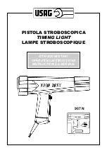


Timing Light 907N
1. GENERAL INFORMATION
The timing light 907N can be used on
2 or 4 stroke petrol engines with up to
2 sparks per revolution. Stroboscopic
RPM and advance measurements are
independent from the number of cylin-
ders and can be carried out by connect-
ing the inductive clamp to the spark
cable of the No.1 cylinder.
DC or peak voltages can be measured
by connecting the RED 1 clip to the test
point. Dwell of each distributors’ cam-
shafts can be measured both in de-
grees or in percentage.
Injection time or duty cycle measure-
ments in milliseconds of injectors or
other actuators can be made by con-
necting the RED 1 CLIP and the induc-
tive clamp to the spark cable of the rel-
evant cylinder.
RPM measurements can be carried out
by the stroboscope, without contact
and without sticking any reflecting
tapes to the rotating part.
2. CHECKS
It is possible to diagnose faults and
wears without disassembling the part
concerned:
1 - in the contact breaker system;
2 - in the centrifugal advance mecha-
nism;
3 - in the timing system;
4 - in the vacuum advance system;
5 - in the vacuum retard system;
6 - in the battery and charging system.
A check and a correct adjusting of the
different parts described above allow
to optimize
the engine performance,
reduce wears, fuel consumption and
harmful gas emissions.
3. PRECAUTIONS
In order to prolong the lifetime of the
unit, it is necessary to softly coil the
cables but never wrap them around the
timing light.
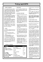
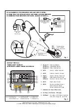
4. OPERATING INSTRUCTIONS
•
Connect the timing light as shown
in Fig. 1.
A reversed connection to battery of
the RED/BLACK clips does not
cause damages to the timing light.
Mount the clamp at about
10 cm
from the distributor
, with the arrow
pointing towards the spark plug.
Make sure the cables are far from
exhaust pipes, rotating parts and
high voltage leads.
•
Check that the coil’s electrical con-
nections are correct. Reversed con-
nections can cause reading un-
steadiness and decrease the engine
performance.
•
Check that the timing marks can be
seen clearly; bring otherwise the
piston of the No.1 cylinder at TDC
in compression stroke, and trace
with a white chalk two signs in line
on the crankcase and the crankshaft
pulley.
•
By pressing the
D
key, the strobe
light should flash regularly; an irreg-
ular flashing could be caused by:
- non-resistive spark cables;
- discharges between cap poles or to
ground due to dirt or moisture;
- leakage to ground or between ca-
bles due to ageing or cracks in the
insulating sheath;
- wear or excessive gap between ro-
tor arm and poles or cap’s central
contact;
- too small spark gap or spark elec-
trodes with too much carbon resi-
dues;
- too low voltage on the spark plug
due to faults in the ignition system;
- timing light too near to spark cables,
distributor or ignition coil.
•
Check against the light that the
clamp’s cores match completely.
With a cloth, remove possible
grease and dust.
5. CHECKING THE DWELL ANGLE
•
Start the engine and make it warm
till reaching a regular rotation at idle.
•
Disconnect the vacuum tube, if
specified in the data manual.
•
In breaker points or transistorized ig-
nition systems, the Dwell angle is
checked by connecting the RED 1
clip to coil negative.
•
In some transistorized systems, a
zero reading means an interrupted
reluctor or wiring. If the reading is
very different from 3
÷
5 ms, the caus-
es can be: a wrong distance be-
tween poles and reluctor, a faulty
module or a resistance of the ground
connection higher than 0.1 Ohm.
Check the ECU, in case it should
directly drive the ignition coil.
•
In case of breaker points systems
follow the instructions in the yellow
sheet to check that the measure-
ment in degrees or percentage cor-
responds to the manufacturer’s
data. Readings out of tolerance can
be due to: wrong distance between
contacts, damages to the
base plate
or the contacts, worn camshaft and
distributor shaft .
•
Bring the engine to 2000 RPM, varia-
tion should not be more than 3 de-
grees (some distributors have higher
variations, it is therefore necessary to
check the features declared by the
manufacturer before changing it).
Higher variations can be due to the
same causes described in the pre-
vious chapter, loose contacts, used
contacts’ pivot.
In case of an excessive variation
when connecting the vacuum tube,
the pivot post of the base plate could
be damaged.
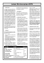
– RPM
400
÷
19.999 rpm
1 rpm
– Stroboscopic advance
0
÷
78
°
/90
°
(400/465 rpm)
0.1
°
– DWELL (for each cylinder)
0
÷
65 ms
0.1 ms
0
÷
100%
0.1%
0
÷
120
°
(> 600 rpm)
0.1
°
– DC Voltage
1
÷
70 Volts
0.1 Volt
– Peak Voltage
1
÷
70 Volts
0.1 Volt
– Stroboscopic RPM counter
60
÷
6000 rpm
1 rpm
– Memory of readings
6 s (from key D release)
– Power supply
9.5
÷
15 Volts (9.5
÷
35 V optional)
READING
SCALE
RESOLUTION
TECHNICAL FEATURES


