

tor or check that the distribution belt
has not jumped a cog.
The same procedure may be used
for checking the marks of centrifu-
gal advance.
In systems with ECU, check the en-
gine temperature sensor.
9. ADVANCE MEASUREMENT
•
Check that the RPM number is the
same shown in the manufacturer’s
data.
•
Press the
C
±
key until the display
shows the number of degrees indi-
cated in the manufacturer’s data.
Lighten the TDC marks on the pul-
ley and crankcase
taking care not
to confuse them with the other
ones
.
Check that the error in the alignment
of TDC marks is within the toleranc-
es foreseen by the manufacturer,
otherwise turn the distributor.
In ECU systems, check that the tim-
ing belt
has not jumped a cog or
that the engine temperature sensor
is not faulty.
•
If the TDC mark swings too much
check the distribution belt and the dis-
tributor mechanisms in point systems.
Note:
In some vehicles, reference
marks can be better lightened by
keeping the timing light in an uncom-
fortable position for the reading.
In this case store the reading when
the marks are aligned by releasing
the key
D
, then read the value with-
in 6 seconds.
10. CENTRIFUGAL ADVANCE
MEASUREMENT
•
Run the engine to the speed indi-
cated in the data manual.
•
Press the
C
±
key until the display
shows the number of degrees indi-
cated in the data manual or in man-
ufacturer’s data; TDC marks on the
crankcase
and on the crankshaft
pulley should be in line.
If the error is excessive, check the
engine temperature sensor in ECU
systems; if the mark swings too
much, or moves irregularly during
accelerations, check that the timing
belt is not loose.
In points systems check the contact
spring; the centrifugal mechanism
No variations or wrong variations
could be caused by: diaphragm of
the vacuum advance variator
cracked.
Note:
In breaker points systems, an
excessive wear of the distributor’s
parts causes abnormal advance
variations and a decreased engine
performance. A too low Dwell angle
causes an insufficient ignition; a too
high Dwell angle causes a prema-
ture burning of contacts.
Remember to check the advance
after repair.
6. CHECKING THE RPM NUMBER
•
Reading up to 19 990 RPM can be
made through the inductive clamp.
Direct measurements up to 6 000
RPM are possible with the strobo-
scope. In this case refer to the yel-
low instruction sheet.
•
In carburettor systems and in some
early electronic injection systems,
adjust the advance through the spe-
cial screw for a correct air/petrol
mixture until obtaining a regular en-
gine rotation.
Note:
A perfect idle adjustment limits
fuel consumption, emission of harm-
ful exhaust gases and avoids engine
stops
.
7. CHECKING BREATHER PIPES
•
The check is made by disconnect-
ing the tubes that go from the crank-
case to the engine head or to the
carburettor. By closing the top of the
tube with a finger, a drop of 50 or
more RPM should occur. If not,
check that there are no filter occlu-
sions or possible damages of the
pipe’s valves.
8. CHECKING THE MECHANICAL
POSITION OF TIMING MARKS
•
To check only the timing marks’ po-
sition, bring the display to 00,1
through the
C–
key.
•
Bring the engine to idle and discon-
nect the vacuum tube or observe the
instructions of the manufacturer.
By pressing the
D
key, the timing
light should flash.
If the timing mark is too far from the
correct position, rotate the distribu-
could otherwise be worn as well as
the pivots or the distributor shaft.
Note:
A faulty centrifugal timing can
result in lack of pick-up and flat
points in engine power at certain
engine speeds.
11. CHECKING THE VACUUM ADVANCE
•
By connecting the vacuum tube,
advance should increase. It can be
measured by bringing TDC marks
in line.
In points systems: if there is no var-
iation or if the advance is too much
out of tolerances, the diaphragm
and the baseplate should be
checked.
Note:
In ECU controlled ignition/injec-
tion systems, if the advance caused
by the vacuum device does not cor-
respond to the manufacturer’s spec-
ifications, it can be due to a wrong
operation of the vacuum sensor.
12. CHECKING THE ACCELERATION
RETARD
This check can be made in engines
provided with this device.
•
Press the
C
±
key to bring the dis-
play to 00,1. By connecting the vac-
uum retard tube during sudden ac-
celerations, the advance should
momentarily decrease.
In case of anomalous variations,
check the diaphragm or other me-
chanical parts.
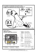
13. VOLTAGE MEASUREMENTS
Measurements of direct battery volt-
age at cranking, alternator’s charge,
voltage variations on temperature sen-
sors, throttle potentiometer, peak volt-
age of TDC inductive sensors, RPM
sensors or the control signal sent by
the ECU to the ignition modules can be
made by connecting the RED 1 clip to
the signal contact.
14. RESET
If the timing light display should show
faults while connecting the RED/
BLACK power clips or during operation,
take the timing light away from possi-
ble noise sources (spark cables, dis-
tributors, alternators) and press RE-
SET.


