background image

13

USSC

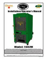
PARTS DIAGRAM AND LIST

38

45

44

46

48

40

37

36

39

41

42

43

47
49

IMPORTANT NOTE:

When ordering repair parts, a color code (G) should be placed 

after the part number of any part that is painted.

Key Description

Part #

Qty

1

Feed Door Assy. (w/Rope Gasket)

69091

1

2

Door Handle

24179

2

N/S

Lock Nut, 1/2-13

83444

2

N/S

Washer

83835

2

3

Spring Handle

89574

4

4

Feed Door Latch

23786

1

5

Ash Door Assy. (w/Rope Gasket)

68880

1

6

Draft Cap

23859

2

N/S

Carriage Bolt, 3/8-16 x 2-1/2”

83835

2

7

Ash Door Latch

23823

1

N/S

Hinge Pin, 5/16” x 1”

C21399

4

8

Shaker Handle

69005

1

9

Bracket, Shaker Handle

24204

1

10

Ash Pan

68882

1

11

Grate Retainer

40312

2

12

Shaker Bar

891341

1

13

Shaker Grate Section

40314

5

14

Back Liner

40313

1

15

Front Liner

40344

1

16

Full Firebrick (4-1/2 wide x 9 tall x 1-1/4 thick)

89066

16

17

Half Firebrick (2-1/4 wide x 9 tall x 1-1/4 thick)

891414

3

18

Slide Baffle

24231

1

19

Baffle Rod

86603

1

20

Lock Nut, 1/2-13

83444

2

21

Gasket, Flue Collar

88032

1

22

Flue Collar

40246

1

23

Flue Collar Ring

22761

1

24

Smoke Curtain

23800

1

25

Smoke Door Clip

23787

2

26

Carriage Bolt, 1/4-20 x 1-1/4 Long

83445

2

27

Kep Nut, 1/4-20

83250

2

28

Cabinet Side, Left

69452

1

29

Cabinet Side, Right

69453

1

30

Blank Receptacle, Snap-In

891127

1

31

Cabinet Back

25624

1

32

Insulation, Panel

C98871

1

N/S

Insulation Retainer

83884

12

33

Cabinet Top

69088

1

34

Front Filler

23817

1

35

Draft Cover

23818

1

36

Room Blower - 800 CFM

80530

2

37

Blower Gasket

88127

2

38

Tinnerman Clip, 1/4-20

83340

8

39

Bolt, 1/4-20 x 3/4

83339

8

40

Conduit Assembly (5ft)

69578

2

41

Snap-disc, 140°F Adjustable

80388

1

N/S = Not Shown

Key Description

Part #

Qty

42

Snap-disc Box

68234

1

43

Conduit Assembly (1.5ft)

68231

1

44

Junction Box

25625

1

45

Insulation (5” x 5”)

25626

1

46

Junction Box Cover

80231

1

47

Rocker Switch

C42373

1

48

Romex Cable Clamp

80362

1

49

Water Coil Access Cover

23819

1

Summary of Contents for Clayton 1602M

Page 1: ...80 www usstove com SAFETY NOTICE If this furnace is not properly installed a house fire may result For your safety follow these installation instructions Contact local building or fire officials about...

Page 2: ...etting the draft adjustment and the chimney to which the unit is attached The actual area that this unit will heat depends on factors such as the conditions of the building heat loss type of construct...

Page 3: ...d slowly it produces tar and other organic vapors which combine with expelled moisture to form creosote The creosote vapors condense in the rela tively cool chimney flue of a slow burning fire As a re...

Page 4: ...m of 1 4 to the foot At no time should the pipe turn downward toward the chimney or run horizontal 2 There should be no more than two 90 degree elbows 3 The connector pipe should never be longer than...

Page 5: ...order to insure proper furnace performance Failure to provide return air ducts of the specified size will void your warranty A filter should be installed in the cold air return Furnace fil ters shoul...

Page 6: ...ting brackets on the left side of the door frames as illustrated The slots in the brack ets and latches are for door seal adjustment Make the proper adjustments then tighten the nuts The door s gas ke...

Page 7: ...the illustration Attach the shorter con duit assembly to the bottom of the box securing it with the nut on the fitting 5 Plug the wires onto the snap disc see wiring sche matic and then attach the box...

Page 8: ...CK REPLACEMENT If baffle replacement is necessary slide the baffle out until you can access the nuts thru the flue outlet Once the nuts have been removed slide the baffle off the rod and thru the open...

Page 9: ...oal in on the shaker grates It should come up to about half of the first firebrick level Place crumpled paper over the coal and crisscross a couple handfuls of dry kindling wood 3 4 in thickness on to...

Page 10: ...a fire extinguisher into the firebox After chimney fire is over completely inspect system for damage before further use NEVERthrowwateronthefireoratthefurnace asrapidly expanding steam could result in...

Page 11: ...ap is not too close to the top of the chimney D Check chimney draft make sure chimney flue pipe is clean and chimney is of adequate height E Make sure you re not suffocating the fire with exces sive a...

Page 12: ...12 USSC PARTS DIAGRAM 11 12 13 16 15 17 14 7 10 5 2 3 6 30 29 4 3 2 1 35 3 8 9 24 26 25 27 17 16 3 19 18 20 28 34 21 22 32 33 23 31...

Page 13: ...ide x 9 tall x 1 1 4 thick 891414 3 18 Slide Baffle 24231 1 19 Baffle Rod 86603 1 20 Lock Nut 1 2 13 83444 2 21 Gasket Flue Collar 88032 1 22 Flue Collar 40246 1 23 Flue Collar Ring 22761 1 24 Smoke C...

Page 14: ...for your home U S Stove offers the model UFB908 as an option and can be purchased from your local dealer The UFB908 utilizes a standard 16 x 20 filter that can be purchased from your local dealer or a...

Page 15: ...al The installation is now ready to be plumbed to your exist ing hot water system Choose one of the three methods described in the Hot Water Coil instructions 6 Remove knockouts from the access panel...

Page 16: ...method with the highest portion of your fire bed in the center of the firebox The first flames will be long and generally orange or yellow and produce quite a bit of smoke As the gases burn off the fl...

Page 17: ...w minutes until the volatile gases have burned off It is not necessary to shake down the ashes each time you refuel the furnace Experience will be your best teacher BULLETIN RC454 A GUIDE TO BURNING C...

Page 18: ...18 USSC NOTES...

Page 19: ...19 USSC NOTES...

Page 20: ...future reference When placing an order or for warranty claims please provide the following information found on the Certification Plate located below the ash door PART NUMBER PART DESCRIPTION MODEL NU...

Reviews: