


2
USSC
INTRODUCTION
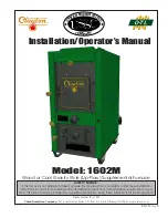
Thank You for your purchase of a U.S. Stove Wood/Coal
Burning Gravity Style (Up-Flow) Furnace. Your decision to
buy our Clayton Furnace was undoubtedly reached af
-
ter much careful thought and consideration. We are very
proud you chose this furnace and trust you will receive
the comfort and economy that others realize when heat
-
ing with a U.S. Stove product.
Your dealer is important in your experience with the fur
-
nace not only with the purchase, but for recommen
-
dations for professional installation in your home. The
qualified professional installer has been expertly trained
in solid-fuel furnace installation to assure the safety and
comfort for your family while saving you money. Trust your
experienced installer. He is a specialist in this field.
IMPORTANT
Before installing and using your Clayton furnace, please
read the following pages thoroughly and carefully. If you
follow the instructions, your Clayton furnace will give you
safe and more dependable service for years to come.
• First step: Check your local codes. This installation must
comply with their rulings.
• Do Not install this furnace in a mobile home or trailer
• Always have a smoke or ionization detector and a CO
detector installed in your home.
• To prevent injury or damage, do not allow anyone
who is unfamiliar with the furnace to operate it.
• This furnace
must be
installed ONLY in the prescribed
manner shown in illustrations 1, 2, or 3 under the
In-
stallation Examples
in this manual. It is
NEVER to be
installed as a counter-flow or down-draft furnace
, or
in any manner wherein the heated air is directed in a
downward flow into the home or toward to an existing
central furnace.
•
NEVER INSTALL
outside the home.
• Spend adequate time with your furnace to become
well acquainted with the different settings and how
each will affect its burning patterns. It is impossible to
state just how each setting will affect your furnace be
-
cause of the variations in each installation.
DISCLAIMER NOTICE
The BTU ranges and heating capacity specifications are
provided as a guide and in no way guarantee the output
or capacity of this unit. The actual BTU output depends
on the type of fuel being burned and its conditions, the
thermostat setting, the draft adjustment and the chimney
to which the unit is attached. The actual area that this
unit will heat depends on factors such as the conditions
of the building, heat loss, type of construction, amount of
insulation, type of air movement, the location of the unit
and more importantly the duct work and return air facility.
Warning:
Do not alter this appliance in any way other than speci
-
fied in these instructions. Doing so may void your warranty.
LOCATING YOUR FURNACE
The furnace is to be installed maintaining the clearances
specified in the following illustrations.
CLEARANCES
REDUCED CLEARANCES
NFPA guidelines and most codes permit reduced clear
-
ances to combustible walls and ceilings if adequate
protection is added. A common mistake is to assume
that sheet metal, masonry, or millboard placed directly
against a wall protects it. Materials installed in this man
-
ner actually provides very little protection. These materials
are good heat conductors, so they will be almost as hot
on their back side as they are on the exposed side. There
-
fore, the combustible wall behind is still a fire hazard.
A wall can be kept cool using these items but only if they
are mounted and spaced out from the wall by an inch
or two to allow free air circulation behind the protective
panel. The protective panel should also have a gap be
-
tween the floor and ceiling.
Three rules to follow when constructing wall protectors:
1. Non-combustibility of all materials including mount
-
ing and supporting.
2. A well ventilated air space between protector and wall.
3. Sufficient strength and rigidity so that the protector
and air space will be durable.
PROTECTIVE COVERING
AND ALL SUPPORTS MUST
BE NON-COMBUSTIBLE
CONSTRUCTING
NON-COMBUSTIBLE
WALLS
2” FROM FLOOR
2” FROM CEILING
1” AIR SPACE
Do not place the furnace directly on a combustible floor.
If you are placing it on a combustible floor, an approved
fire retardant material, equivalent to 3/8” UL Listed mill
-
board, should be placed under the unit. The material must
extend at least 16 inches beyond the front of the unit and
8 inches on either side of the fuel loading door opening.
It must also extend underneath the chimney connector
and to each side of the connector by at least 2 inches.
22”
12”
20”
15”
COMBUSTIBLE WALL
COMBUSTIBLE WALL
FLUE
(TOP VIEW)
MINIMUM CLEARANCES
TO A COMBUSTIBLE
WALL
CAUTION:
DO NOT store
combustible or
flammable materials or
liquids near the
furnace.
Summary of Contents for Clayton 1602M
Page 18: ...18 USSC NOTES...
Page 19: ...19 USSC NOTES...


