background image


While in the search mode, the remote search icon   

  will be constantly displayed. 


Note: 

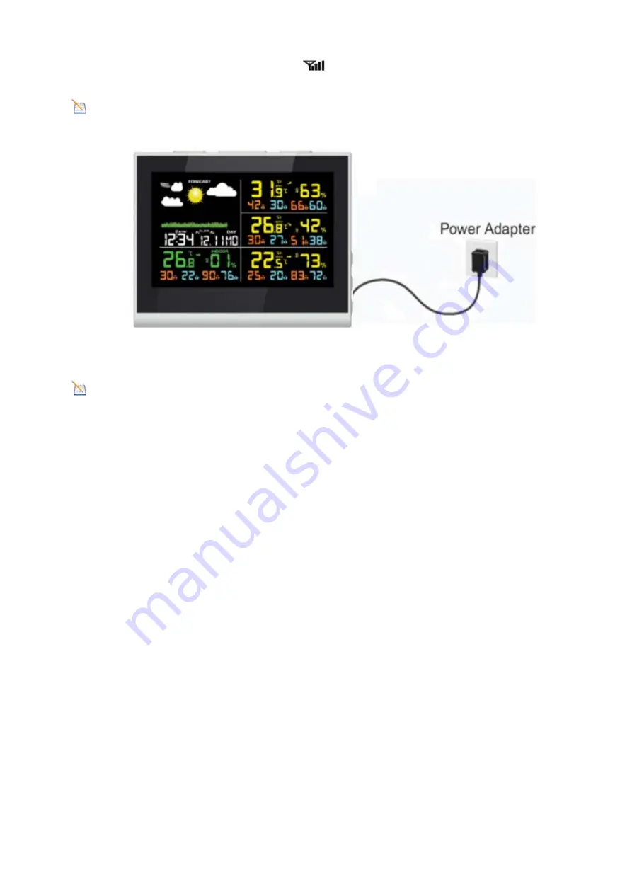
The power adapter is intended to be correctly oriented in a vertical or floor mounted position. The prongs 

are not designed to hold the plug in place if it is plugged into a ceiling, under-the-table or cabinet outlet. 


Figure 4 


Note:

 If the power adapter is plugged in, 

AC ON

 will display in the time area for three seconds when powered 

up. Conversely, if the power adapter is not plugged in, 

AC OFF 

will be displayed. 


2.3.3


Sensor


Operation


Verification


The following steps verify proper operation of the sensors prior to installing the sensor array.   
1. Verify proper operation of the indoor and outdoor temperature. Verify the indoor and outdoor temperature match 
closely with the console and sensor array in the same location   
(about 3m apart). The sensors should be within 2°C (4°F) (the accuracy is 

±

1°C/2°F). Allow about 30 minutes for 

both sensors to stabilize.   

2.


Verify proper operation of the indoor and outdoor humidity. Verify the indoor and outdoor humidity match closely with 

the console and sensor array in the same location (about 3m apart). The sensors should be within 10% (the accuracy is 

±


5%). Allow about 30 minutes for both sensors to stabilize 


3.


Weather


Station


Installation


3.1


Best


Practices


for


Wireless


Communication


Wireless communication is susceptible to interference, distance, walls and metal barriers. We recommend the following 
best practices for trouble free wireless communication.   
1. 

Electro-Magnetic Interference (EMI)

. Keep the console several feet away from computer monitors and TVs.   

2. 

Radio Frequency Interference (RFI). 

If you have other 433 MHz devices and communication is intermittent, try 

turning off these other devices for troubleshooting purposes. You may need to relocate the transmitters or receivers to avoid 
intermittent communication.   
3. 

Line of Sight Rating. 

This device is rated at 100 m line of sight (no interference, barriers or walls) but typically you will 

Summary of Contents for FT0851

Page 1: ...e FT0851 weather station consists of the following parts as referenced in Figure 1 QTY Item 1 Display Console Frame Dimensions LxHxW 135X195X26mm LCD Dimensions LxW 112 x 63mm 3 Thermo hygrometer sens...

Page 2: ...1 Display Console Layout The display console layout is shown in Figure 2 Note The following illustration shows the full segment LCD display for description purposes only and will not appear like this...

Page 3: ...he console or the console will time out searching for the sensors Power the console last Make certain the weather station sensor array is at least 3m away from the console and within 30m of the consol...

Page 4: ...Allow about 30 minutes for both sensors to stabilize 2 Verify proper operation of the indoor and outdoor humidity Verify the indoor and outdoor humidity match closely with the console and sensor arra...

Page 5: ...on range by the factor shown below Medium RF Signal Strength Reduction Glass untreated 5 15 Plastics 10 15 Wood 10 40 Brick 10 40 Concrete 40 80 Metal 90 100 3 2 Remote Sensor Installation If you moun...

Page 6: ...SNOOZE LIGHT button CHANNEL button on the top and SET button ALARM button and C F WiFi button on the right side Note WiFi Settings reference 10 STEP 5 1 Set Program Mode While in Normal Mode press an...

Page 7: ...e current channel outdoor unit and re search the current channel for 3 minutes When searching the channel will be re registered 5 3 Reset Min Max record Press the MIN MAX button once to check the MAX...

Page 8: ...n on for five seconds and if no operation is performed for three seconds the backlight will turn off Press and hold the LIGHT key for two seconds and the backlight will turn on permanently and display...

Page 9: ...e will begin flashing Press the or key to increase or decrease the temperature reading in increments of 0 1 Press and hold the or key for three seconds to increase or decrease rapidly Press the ALARM...

Page 10: ...of time In normal mode Press and hold the ALARM key for three seconds to enter the alarm1 settings mode The alarm parameter will begin flashing In alarm mode press the SET key to the alarm2 settings m...

Page 11: ...e server to obtain the time Once the connection succeeds and the console s time has updated the SYNC icon will appear on the LCD The time will automatically synchronize to the internet per an hour Not...

Page 12: ...t phone tablet or computer to connect to the console through WiFi Note that when the console programming is complete you will resume your default WiFi connection Note that you cannot connect two or mo...

Page 13: ...nnect to the WeatherHome WiFi network as shown in Figure 9 your WiFi network name may be slightly different but will always begin with WeatherHome Figure 9 10 4 Example 4 Connect to the console WiFi s...

Page 14: ...e following information into the web interface Figure 11 Make sure all of the information is entered prior to selecting Save If you choose not to use Upload Wunderground com Upload AmbientWeather net...

Page 15: ...ve a hidden SSID enter the SSID manually Time Zone Settings default 0h based on the number of hours from Coordinated Universal Time or Greenwich Mean Time GMT The following table provides times zones...

Page 16: ...CET Central European Paris France 2 EET Eastern European Athens Greece 3 BT Baghdad Moscow Russia 4 Abu Dhabi UAE 5 Tashkent 6 Astana 7 Bangkok 8 CCT China Coast Bejing 9 JST Japan Standard Tokyo 10...

Page 17: ...ure If the data signal icon is updata to weather servers the icon will flash If the icon disappears it means the console is not connected to the weather servers more than half an hour or no choose the...

Page 18: ...ew your data as shown in Figure 16 Figure 16 AmbientWeather net is a responsive design and mobile friendly so there is no need for a mobile app Simply open your mobile devices web browser browse to Am...

Page 19: ...derground com personal weather station dashboard ID STATIONID where STATIONID is your personal station ID example KCALOSAN782 Figure 18 Note The current temperature and humidity data is the transmitte...

Page 20: ...connects to IFTTT the platform that allows devices and services to work together seamlessly Here are a few things you can do with IFTTT Turn off your Rachio sprinklers when it rains there is too much...

Page 21: ...t Link your account to get started say hey google Ambient Weather weather report This will provide you with your outdoor weather report You can ask for your indoor weather report as well by saying ind...

Page 22: ...Note This is best done on a computer desktop or laptop 10 15 6 Visit https weathercloud net and enter a Username Email and Password as shown in Figure 22 Figure 22 10 15 7 Respond to the validation e...

Page 23: ...p AC the console or press and hold the MIN MAX WiFi button for three seconds in normal mode the console icon above the DAY icon will flash to signify that it has entered WAP wireless access point mode...

Page 24: ...cally restart it is not the console to reset 11 7 Once the upgrade is completed the console will automatically exit WAP mode 12 Specifications 12 1 Wireless Specifications Line of sight wireless trans...

Page 25: ...WAP mode smart device including laptops computers smart phones and smart pads 4 Recommend web browser for setup UI Web browser support of HTML 5 such as the latest versions of Chrome Safari IE Edge Fi...

Page 26: ...ay time Make sure the thermo hygrometer is mounted in a shaded area The pre preferred location is a north facing wall because it is in the shade most of the day Indoor and Outdoor Temperature do not a...

Page 27: ...an be determined by turning the equipment off and on the user is encouraged to try to correct the interference by one or more of the following measures Reorient or relocate the receiving antenna Incre...

Reviews: