background image

22

Duct pressure switches and sensors

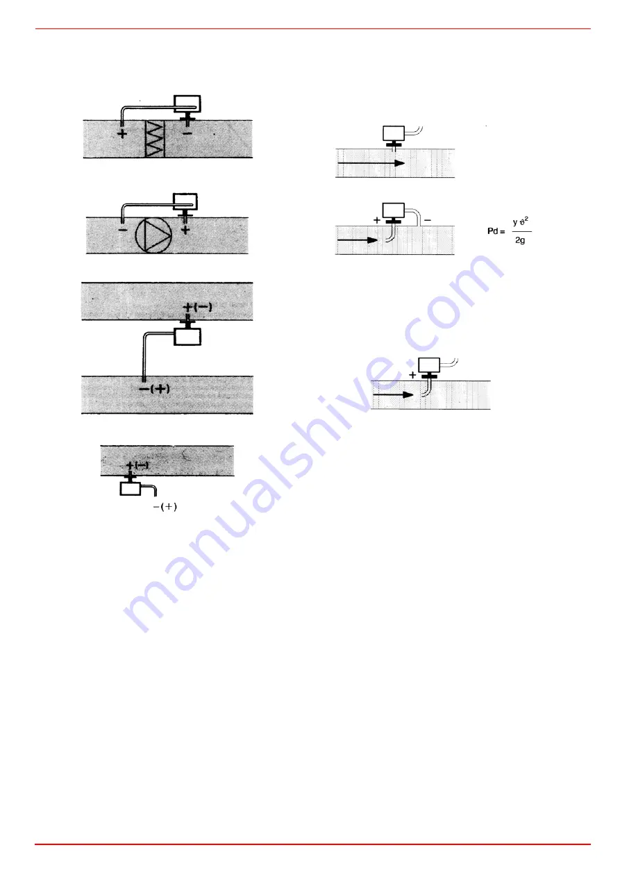
Installing differential pressure probes for air

A - Control a filter (clogging)

B - Control a fan (upstream/downstream)

C - Measurement of difference in pressure between two ducts

D - Measurement of difference in pressure between two rooms or 

of inside of duct and outside

Basic principles

Measuring static pressure(i.e. pressure exerted by air on pipe 

walls)


Measuring dinamic pressure 

Legend

y

Kg/m3, specific weight of air

q

m/s, air speed

g

9.81 m/s2 gravity acceleration

Pd

mm C.A., dynamic pressure

Measuring total pressure

Summary of Contents for PBY1025

Page 1: ...MANUAL OF INSTALLATION USE MAINTENANCE PBY1025 PBY1030 PBY1040 M039126CE Rel 4 3 04 2017 BURNERS BRUCIATORI BRULERS BRENNER QUEMADORES Progressive Fully modulating Heavy oil Burners...

Page 2: ...e employed exclusively for the use for which it was designed Before connecting the burner make sure that the unit rating is the same as delivery mains electricity gas oil or other fuel Observe caution...

Page 3: ...gaseous fuels 2014 35 UE Low Tension Directive 2014 30 UE Electromagnetic compatibility Directive 2006 42 EC Machinery Directive Harmonized standards UNI EN 676 Automatic forced draught burners for ga...

Page 4: ...s oil and solid fuel burning appliances having electrical connections UNI EN ISO 12100 2010 Safety of machinery General principles for design Risk assessment and risk reduction National Standard UNI 7...

Page 5: ...ovided on the site All burners are ignited by means of a pilot flame burning LPG or Natural gas The standard ver sion of the burner uses compressed air to atomize oil fuel If compressed air is not ava...

Page 6: ...FUEL H heavy oil viscosity 4000cSt 530 E 50 C 3 OPERATION Available versions PR Progressive MD Fully modulating 4 BLAST TUBE S Standard L Extended 5 DESTINATION COUNTRY see data plate 6 BURNER VERSIO...

Page 7: ...bustion head is set in order to find a compromise between the burner output and the generator specifications that is why the minimum output may be different from the Per formance curve minimum The bur...

Page 8: ...Y1025 1784 1980 377 25 304 404 335 376 572 641 1408 680 1312 680 632 472 522 660 815 M16 651 460 460 x x 265 80 49 1145 379 330 PBY1030 1761 2006 377 25 138 608 589 353 598 657 1408 680 1312 680 632 6...

Page 9: ...or 19 Maual valve 20 Pressure gauge 21 Flexible hose COMPRESSED AIR TRAIN ATOMIZATION 40 Pressure governor with filter 41 Pressure gauge 42 Solenoid valve 43 Pressure switch 44 One way valve 45 Meteri...

Page 10: ...ng valve with servomotor 18 Actuator 19 Maual valve 20 Pressure gauge 21 Flexible hose COMPRESSED AIR TRAIN ATOMIZATION 40 Pressure governor with filter 41 Pressure gauge 42 Solenoid valve 43 Pressure...

Page 11: ...lace the burner towards the furnace plate lift and move the burner by means of its eyebolts placed on the top side see Lifting and moving the burner 3 screw the stud bolts 5 in the plate holes accordi...

Page 12: ...rner s main switch is in 0 position OFF too Read carefully the chapter WARNINGS and the Electrical connections section WARNING The burner is provided with an electrical bridge between terminals 6 and...

Page 13: ...d for three phase 400 V supply and in the case of three phase 230 V supply it is necessary to modify the electrical connections inside the terminal box of the electric motor and replace the thermal cu...

Page 14: ...provided that is a system to heat pipes and plant components to mantain the viscosity in the pumping lim its Higher the oil viscosity and lower the ambient temperature more necessary the pipe heating...

Page 15: ...1 4 48 150 19 3 128 14 48 43 2 5 92 200 23 5 170 18 9 54 7 35 250 28 212 23 45 65 8 79 300 32 5 254 28 87 6 11 7 400 41 9 338 37 1 110 14 6 500 51 6 423 46 2 132 17 5 600 61 4 508 55 4 154 20 45 700 7...

Page 16: ...0 30 40 50 60 70 80 90 100 110 120 130 140 150 160 TEMPERATURE C VISCOSITY E LIGHT OIL 1 3 E AT 20 C HEAVY OIL 2 4 E AT 50 C HEAVY OIL 4 E AT 50 C HEAVY OIL 7 5 E AT 50 C HEAVY OIL 10 E AT 50 C HEAVY...

Page 17: ...ure at the pump inlet should be 80 C see diagram Indicative diagram showing the oil pressure according to its temperature OIL TEMPERATURE FOR PUMP FEEDING 1 10 100 0 10 20 30 40 50 60 70 80 90 TEMPERA...

Page 18: ...1 Main tank 10 Daily tank OIL PUMPING UNIT 11 Heating device 2 Manual valve 12 Electrical resistor 3 Filter 13 Pressure gauge 4 Pump coupled to electrical motor 14 High pressure switch PO MAX 5 Safet...

Page 19: ...gas supply network must be carried out Once the gas train in installed execute the electrical connections for all its items gas valves group pressure switch ATTENTION once the gas train is mounted ac...

Page 20: ...bar Min inlet pressure 0 4bar For further details see the manifacturer documentation Key EVG Light oil solenoid valve M Manometer P Pump Fig 17 Suntec TV Pressure governor Pressure adjustment Remove c...

Page 21: ...ction threads elbow joints and couplings should be sealed with removable sg component The number of jun ctions should be kept to a minimum as they are a possible source of leakage z Do not use PTFE ta...

Page 22: ...l hoses to the pump proceed as follows according to the pump provided 1 remove the closing nuts H on the heater and R on the oil pressure governor of the inlet and return connections 2 screw the rotat...

Page 23: ...C I B UNIGAS M039126CE 23 Hydraulic connections Key G Gas A Compressed Air O Oil Fig 21 G G O A A O...

Page 24: ...bon monoxide if this should happen make the fuel decrease slowly until the normal combustion values are achieved Before starting up the burner make sure that the return pipe to the tank is not obstruc...

Page 25: ...zles that suit the boiler utilisation output and setting the delivery and return pressure values according to the ones quoted in the diagram below as far as reading the pressure values see next paragr...

Page 26: ...ture must be set during burner operation checking temperature in the thermometer mounted on the pre heating tank We suggest a thermometer with scale up to 200 C Fig 23 Danfoss MCX Fig 24 Probe connect...

Page 27: ...next picture Screw to increase the pressure unscrew to decrease once the regulation is performed replace cap T Adjust this thermostat to the correct value according to the visco sity temperature diagr...

Page 28: ...ged 2 bleed the air from the SA port by loosing the cap T without removing it then release the contactor and fasten cap T 3 Before starting the burner up drive the high flame actuator microswitch matc...

Page 29: ...the pressure on the oil preaaure gauge on Fig 25 and act on on the pump governor adjusting screw VR see Fig 29 and description on page 20 as to get the nozzle pressure at 2bar see step 8 If the requir...

Page 30: ...ve 15 as for the point to point regulation in order to set the cam foil shape move the low flame microswitch cam III a little lower than the maximum position 90 16 set the TAB thermostat to the minimu...

Page 31: ...e paying attention to use the CMF switch intead of TAB The CMF position sets the oprating stages to drive the burner to the high flame stage set CMF 1 to drive it to the low flame stage set CMF 2 To m...

Page 32: ...OWN TAKES PLACE CALL THE TECHNICAL SERVICE WITHOUT TRYING TO RESET FURTHER WARNING DURING NORMAL OPERATION THE PARTS OF THE BURNER NEAREST TO THE GENERATOR COUPLING FLANGE CAN BECOME VERY HOT AVOID TO...

Page 33: ...mp M Plant enabling thermostat lamp MD Siemens modulator on fully modulating versions only N Oil pump in operation O Pilot solenoid valve lamp PL Light oil operation lamp PH Heavy oil operation lamp Q...

Page 34: ...y see page 37 z Examine the detection current see page 37 z Remove and clean page 37 the heavy oil nozzle Important use solvents for cleaning not metallic tools and at the end of the maintenance proce...

Page 35: ...t with compressed air or replace it if necessary z reassemble the filtering part in its initial position checking that it is placed in its own slots see Fig 37 z reassemble the bottom cover 3 being su...

Page 36: ...ew and remove it place the new electrode being careful to observe the measures in mm shown on next pictures and reassemble following the reversed procedure 5 To adjust the nozzle position unscrew the...

Page 37: ...s the cleaning of the combustion head the position of the photore sistor and if necessary replace it Cleaning and replacing the detection photoresistor When cleaning the photoresistive detector always...

Page 38: ...NG OPE RATION MAIN SWITCH OPEN z LINE FUSE INTERVENTION z MAX PRESSURE SWITCH FAULT z z FAN THERMAL CUTOUT INTERVENTION z AUXILIARY RELAIS FUSES INTERVENTION z CONTROL BOX FAULT z z z z z SERVOCONTROL...

Page 39: ...3 IGNITION TRANSFORMER 12 PHOTORESISTOR 21 8 1 THROTTLE SHAFT 25 4 1 THERMOSTAT 13 PUMP 21 8 2 BRACKET 25 4 2 THERMOSTAT 14 BRACKET 21 8 3 ADJUSTING CAM 26 1 BOARD 15 STANDARD BLAST TUBE 21 8 3 1 ADJ...

Page 40: ...C I B UNIGAS M039126CE 40...

Page 41: ...iary switch v in the actuator t5 Interval On completion of t5 terminal 20 receives power At the same time control outputs 9 to 11 and input 8 are galvanically separated from the LAL s control section...

Page 42: ...rtup sequence Specifications Power supply AC 230 V 15 10 for LAL2 on request AC 100 V 15 AC 110 V 10 Frequency 50 Hz 6 60 Hz 6 Absorption AC 3 5 VA Mounting position optional Protection IP 40 Perm inp...

Page 43: ...terminal 7 start delay time for M2 t8 Duration of startup sequence excluding t11 and t12 t10 Interval from startup to the beginning of the air pressure check t11 Air damper running time to the OPEN p...

Page 44: ...a L Galvani 9 35011 Campodarsego PD ITALY Tel 39 049 9200944 Fax 39 049 9200945 9201269 web site www cibunigas it e mail cibunigas cibunigas it Note specifications and data subject to change Errors an...

Page 45: ...TRICI SE12 088 PBY1025 progressive burners bruciatori progressivi SE12 090 PBY1025 fully modulating burners bruciatori modulanti SE12 087 PBY1030 progressive burners bruciatori progressivi SE12 089 PB...

Page 46: ...WARNING 1 Power supply 400V 50Hz 3N AC with neutral 2 Don t reverse phase with neutral 3 Ensure the burner is properly earthed Si raccomanda di eseguire i collegamenti esterni di alimentazione in mod...

Page 47: ......

Page 48: ......

Page 49: ......

Page 50: ......

Page 51: ......

Page 52: ......

Page 53: ......

Page 54: ......

Page 55: ......

Page 56: ......

Page 57: ......

Page 58: ......

Page 59: ......

Page 60: ......

Page 61: ......

Page 62: ......

Page 63: ......

Page 64: ......

Page 65: ......

Page 66: ......

Page 67: ......

Page 68: ......

Page 69: ......

Page 70: ......

Page 71: ......

Page 72: ......

Page 73: ......

Page 74: ......

Page 75: ......

Page 76: ......

Page 77: ......

Page 78: ......

Page 79: ......

Page 80: ...C I B UNIGAS S p A Via L Galvani 9 35011 Campodarsego PD ITALY Tel 39 049 9200944 Fax 39 049 9200945 9201269 web site www cibunigas it e mail cibunigas cibunigas it...

Page 81: ...RWF55 5X RWF55 6X User manual M12926CA Rel 0 2 11 2023...

Page 82: ...2 DEVICE INSTALLATION Fixing system Drilling dimensions...

Page 83: ...age 1 Controlling element OPEN stage 2 Operating mode 2 stage Actual value display red and parameter value USB led Operating mode 2 stage Thermal shock protection Alarm function Increase value Enter b...

Page 84: ...change the set point on the upper display red Push Enter to confirm and push ESC more times to get the home position Parameter level Parameter level PArA Pb1 dt rt db tt Heating controllerHYS1 HYS2 HY...

Page 85: ...burner switches back on 1N 1P closes Switch off differential 2 stage HYS2 0 0 HYS3 3 enable only with parameter bin1 4 Upper switch off differential HYS3 0 0 9999 digit 5 Value over setpoint above wh...

Page 86: ...d down arrows according to the tables here below ConF InP InP1 bold factory settings Parameter Value Description SEn1 type of sensor for analog input 1 1 Pt100 3 wire 2 Pt100 2 wire 3 Pt1000 3 wire 4...

Page 87: ...3 0 10V 4 0 5V 5 1 5V 1 0 20mA OFF2 Sensor offset 1999 0 9999 Correction value measured by the sensor SCL2 scale low level 1999 0 9999 minimum scale value for input ohm mA V SCH2 scale high level 1999...

Page 88: ...Free 1 Locked Self optimization can only be disabled or enabled via the ACS411 setup program Self optimization is also disabled when the parameter level is locked oLLo set point limitation start opera...

Page 89: ...multifunctional relay K6 terminals 6N and 6P is activated depending on the switching characteristic The alarm function can have different switching functions lk1 to lk8 and can be set to a deviation...

Page 90: ...setpoint to be monitored see alarm functions lk1 to lk8 limit value AL Limit value range for lk1 and lk20 9999 HySt switching differential 0 1 9999 Switching differential for limit value AL ACrA respo...

Page 91: ...or upper display 0 display power off 1 analog input 1 InP1 value 2 analog input 2 InP2 value 3 analog input 3 InP3 value 4 controller s angular positioning 6 set point value 7 end value with thermal s...

Page 92: ...setting fun ction which recalculates PID values for its operation deciding which are most suitable for the specific kind of request Follow the below instructions push the UP and DOWN arrows for more...

Page 93: ...e upper setpoint limit SPH of the men Crtr The system also prevents the lower working range limit oLLo and upper working range limit oLHi from exceeding dropping below the system temperature limits Th...

Page 94: ...loat WR Actual setpoint 0x0008 R W Float SP1 Setpoint 1 0x000A R W Float SP2 dSP Setpoint 2 0x1035 R O Float Analog input InP3 unfiltered 0x1043 R O Float Actual angular positioning 0x1058 R O Word B1...

Page 95: ...ing range limit 0x107F R O Float oLHi Upper working range limit 0x106D R W Word FnCt Alarm relay function 0x106F R W Float AL Alarm relay limit value limit value alarm 0x1071 R W Float HYSt Alarm rela...

Page 96: ...limitation Bit 9 Control system Bit 10 Self optimization Bit 11 Second setpoint Bit 12 Measuring range overshoot InP1 Bit 13 Measuring range overshoot InP2 Bit 14 Measuring range overshoot InP3 Bit 1...

Page 97: ...17 Electric connections With 7 pins connector version With terminals version Corrispondences bornes entre RWF55 5x y RWF40 0x0Matches terminals betweenRWF55 5x and RWF40 0x0...

Page 98: ...0mA 0 16bar 16 0 0 1600 needless 0 1600 0 5 20 80 0 80 600 kPa Probe 4 20mA 0 25bar 16 0 0 2500 needless 0 2500 0 5 20 80 0 125 600 kPa Probe 4 20mA 0 40bar 16 0 0 4000 needless 0 4000 0 5 20 80 0 200...

Page 99: ...g is of paramount importance It s good to be admired even better to be effective Heating systems the room sensor must not be installed in rooms with heating units complete with thermostatic valves Avo...

Page 100: ...by hot air coming from the pipe Bend 0 4m sensor by hand never use tools as illustrated Installing differential pressure sensors for water Installation with casing facing down not allowed With tempera...

Page 101: ...ibitor on a min 100mm length of pipe Sensors come with straps for pipes up to 100 mm in diameter Placing the probes QAD22 QAE21 QAP21 RCA With pumps on outlet with 3 ways valves with 4 ways valves Pan...

Page 102: ...ce in pressure between two ducts D Measurement of difference in pressure between two rooms or of inside of duct and outside Basic principles Measuring static pressure i e pressure exerted by air on pi...

Page 103: ......

Page 104: ...23 Note Specifications and data subject to change Errors and omissions excepted...

Page 105: ...4 terminals AI4 COM controls the inner heater temperature As soon the relevant set point is got it drives the output number 4 terminals C4 NO4 linked to the relais KTCN This allows the oil pump to sta...

Page 106: ...r temperature probe input AI2 probe Pb2 set point tCI plant consent temperature probe when installed input AI3 probe Pb3 set point OIL oil heater output temperature probe PID regulation input AI4 prob...

Page 107: ...gin first CnF Configuration menu Parameter configuration rEG Regulation menu Set to set point probe thresholds etc ALA Alarm menu Access to alarm management Act Active alarms Show the active alarms rE...

Page 108: ...9 30 0 A4P 2 3 11 A4C Calibration Probe 4 Don t modify it 20 0 20 0 0 0 C A4P 0 3 12 dI Digital input 1 dI1 Input 1 polarity Pump Change type of digital input NC o NO 0 1 1 3 13 dI2 Alarm polarity fr...

Page 109: ...Startup number Don t modify it 0 5 2 3 36 tU3 Measurement cycles number Don t modify it 1 4 2 3 37 tU4 Max differential command exit Don t modify it 0 01 10 00 10 00 V 3 38 tU5 Differential reduction...

Page 110: ...pe of regulation of probe 3 Oil tank exit Type of regulation 0 thermostat 1 PID don t modify 0 1 1 3 50 OIL Set point Probe 3 Oil tank exit Nozzle oil temperature according to the table Set point adju...

Page 111: ...p24 DerivativeTime Td for PID Probe 1 Tank resistor Derivative time for second PID regulation 0 0 300 0 23 0 s rE3 1 3 66 p25 Overshooting for Integral action Tank resistor Don t modify it 100 1000 2...

Page 112: ...bout 1 5 E which guarantees correct and safe functioning of the burner The temperature values in the table guarantee the respect of that parameter and are valid when the pre heating tank is installed...

Page 113: ......

Page 114: ......

Page 115: ......

Page 116: ......

Page 117: ......

Page 118: ......

Page 119: ......

Reviews: