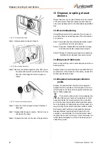
Operating elements and functions
PG-I Series | Version 1.03
11
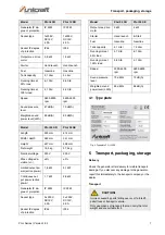
6.3.2Control panel PG-I 12 SR
Fig. 8: Control panel PG-I 12 SR
1 Energy saving switch
2 Motor switches
3 Indicator lights for oil, overload and AC
4 DC circuit breaker
5 Consumer connection 12 V
6 Ground connection
7 Consumer connection 230 V
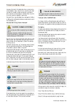
6.3.3Control panel PG-I 20 SR
Fig. 9: Control panel PG-I 20 SR
1 Energy saving switch
2 Motor switches
3 DC circuit breaker
4 Consumer connection 12 V
5 Consumer connection 230 V
6 Ground connection
7 Consumer connection 230 V
8 Indicator lights for oil, overload and AC
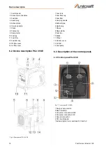
6.3.4Control panel PG-I 35 SE
Fig. 10: Control panel PG-I 35 SE
1 Energy saving switch
2 Indicator lights for oil, overload and AC
3 consumer connection 230 V
4 Ground connection
5 Consumer connection 230 V
6 Electric starter, On / Off switch
7 Consumer connection 12 V
8 DC circuit breaker
7
Operating elements and func-
tions
Energy saving function
When the switch is in the "ON" position, the system con-
trols the motor speed according to the connected electri-
cal load. This improves fuel consumption and noise
emissions. When the switch is in the "OFF" position, the
engine speed remains constant.
1
2
3
6
7
5
4
1
2
3
4
7
5
6
8
NOTE!
The energy-saving switch must be set to "OFF" if
electrical loads are used that require a high starting
current, such as compressors, pumps or cooling
units.
1
2
3
6
8
7
5
4


