background image

36

Keep your tools clean. Dirt may enter the inner mechanism of your machine and cause damage. 

Do not use aggressive cleaning solution or paint thinners to clean the machine. 

Clean plastic parts with cloth dipped in soup water. 

Clean and lubricate metal surfaces with a cloth dipped in paraffin oil. 

If you are not using your machine, lubricate it with suitable grease and store it in a dry place to prevent

corrosion.

Lubrication 

Lubricate working surfaces with suitable grease regularly.

When the operational life of your device is over, dispose off it in accordance with valid rules and regulations.

Your product is made of metal and plastic parts that may be recycled when separated. 

1. Disassemble all parts. 

2. Separate all parts according to the material they are made of (e.g. metals, rubber, plastics, etc.). 

Take the separated parts to the recycling facility near you. 

Information about the locations of recycling centres may be found at your local City office or throughout an

Internet search.

If the machine breaks down, send it back to the vendor for quick repair. 

Please, enclose brief description of the defect. That makes repair easier. If the machine is still covered by

warranty, enclose the warranty card and proof of purchase receipt. After the warranty period expires, we

repair your machine for a special price. 

To prevent possible damages during shipping, packed the machine carefully or use the original packaging

material. We are not liable for shipping damages due to incorrect packaging of your machine. If making

a claim at the shipping company the level and method of packaging plays a major role during claim evaluation

process. 

Note:

Pictures and contents in this manual may slightly differ from the actual product or accessories. 

It is due to continuous improvement of our products. Such small differences have no effect on the product

functionality.

DISPOSAL 

CAUTION 

MAINTENANCE 

5

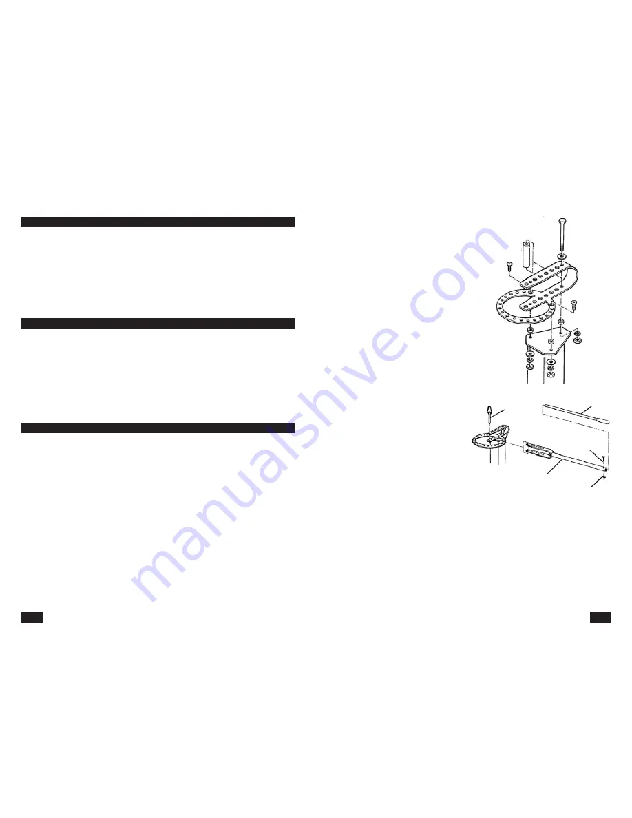
Assembling procedure

Connect the bent part with the round base,

using screw 3/8", flat washer, thick distance

washer (that is placed on the screws inside

the fold), thin distance washers, spring washers

and nuts. 

Place the bent part of the handle (with the holes)

inside the base fold and secure in place with

one or both long connecting studs. 

Remove the clamp from the handle stud and pull

the stud out. Pull the extension arm out, push

the stud in the inner hole and replace the clamp

back. 

Put the machine in final position, where it will

be used. Turn the handle in both directions, to

make sure that no obstacles are within the reach

of the handle. 

Make sure that there is enough space behind the machine to handle long work pieces. If you need to

place the machine close to a wall, tray to place it according to the drawing on the picture.

CAUTION:

Do not use the machine if it is not securely mounted to a work table or to the floor. Severe 

injuries may occur.

screw 3/8"

thick

distance

spacer

flat washer

thin distance
spacer

elastic washer
nut

flat washer 

elastic washer 

nut

mount
stud

extension 

arm

handle

safety pin

handle stud

Summary of Contents for CB200

Page 1: ...t present the warranty card showing the date of the purchase the serial number of the machine vendor stamp and signature of sales clerk as well as the proof of purchase receipt 5 Warranty claim shall...

Page 2: ...rform professional bending work of various type of metal struts and poles with various cross cut sections flat square and circular Equipped with a telescopic arm length up to 90 cm ensures enough powe...

Page 3: ...not used correctly Always pay attention to safety instructions on the safety labels Do not remove or damage them If the warning label becomes unreadable please contact your vendor Disorganized and dir...

Page 4: ...he work piece and subsequently the bending handle Before bending always push the connecting studs all the way in Never try to attempt to bend thermally hardened materials Only hot rolled steel may be...

Page 5: ...packaging material We are not liable for shipping damages due to incorrect packaging of your machine If making a claim at the shipping company the level and method of packaging plays a major role dur...

Page 6: ...the work piece from the machine turn it around or put it back backwards Hole identification in the moveable and non moveable parts of the machine The samples included in this manual have the bracket...

Page 7: ...on an identical piece of material Due to the resiliency of the material the bend has tendency to come back a little After you test the angle and the bend write all the information about the used dies...

Page 8: ...ut if you are performing special bending work or need to bend with high precision it is good idea to fasten the work piece to the stopper cube using self locking pliers see picture on the right Using...

Page 9: ...measurement of the finished bend Round pole bending REQUIRED MATERIAL only for this sample One piece of pole rod with length 228 6 mm and diameter of 15 9 mm Too flat pieces with desired dimensions N...

Page 10: ...114 3 mm and with cross section 25 4 x 4 8 mm NOTE if you are to make similar holder with different dimensions you must first test which die size and what position of the cube best fits your design U...

Page 11: ...ure C Slide the work piece as far as possible against the centre stud Place the stopper stud in the sixth hole of the ring counting from the closed ring end clockwise Turn the handle and perform the s...

Page 12: ...the long connecting stud to fasten the handle brackets and the rings through the centre stud hole Place 25 4 mm 1 die on the centre stud Using the short connecting stud mount the 50 8 mm 2 die in the...

Page 13: ...Mark 13 Bracket screw bending The following charts show the applicable settings for bracket screw manufacture with typical end length and bent radius manufactured from steel poles of common diameters...

Page 14: ...steel bar 225 4 mm long 1 flat steel bar 152 4 mm long BENDING PROCEDURE Make the letter B parts the straight and the arch piece Final steps Stitch weld both parts together Grind and sandblast all sha...

Page 15: ...d No 2 Turn the piece see picture B and slide it toward the mark No 2 and perform 73 angle bend Check the angle Remove the stud that holds the sharp angle die in place Remove it from the machine Final...

Page 16: ...flat steel bar 177 8 mm long 1 flat steel bar 152 4 mm long 1 flat steel bar 63 5 mm long BENDING PROCEDURE flat steel bar 177 8 mm long Mark the locations of the bends See the picture Bend Slide the...

Page 17: ...225 4 mm 1 bar length 152 4 mm BENDING PROCEDURE Using a chalk mark the bend location on both flat rods length 225 4 mm See the picture Bend No 1 Slide the work piece in the machine all the way to the...

Page 18: ...bar 152 4 mm long 1 flat steel rod 95 3 mm long Final steps Weld it together as seen on the picture Make sure to check the 90 angle between both arms Grind and sandblast all sharp edges 76 2 mm REQUIR...

Page 19: ...nd Check the angle Remove the stud that holds the sharp angle die in place Remove it from the machine Final steps Place the long piece 76 2 mm long to a position as shown on the picture and stitch wel...

Page 20: ...52 4 mm long to the finished arch Grind and sandblast all sharp edges Mark 21 REQUIRED MATERIAL Flat steel bar thickness 4 8 mm max width 50 8 mm 1 flat steel rod 369 9 mm long 1 flat steel rod 63 5 m...

Reviews: