-5-
Control valve testing:
Once filled with water, and before use, or if the system has been drained down for a period of time, it is
important to check the operation of the valve – switch on the control panel and set the temperature to a high
level (temperature altered by raising the set point). This is done by:
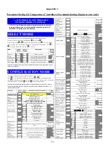
•
press
which is too the right of the temperature display.
•
The lower display will then show “SP” and the upper display will show the actual set point.
•
Press
or
to change the set point to the required value.
•
Finally, press
to return to normal run mode.
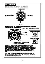
The actuator should slowly rotate clock wise until the valve is at the “2 O’clock” position and then stop. Now
lower the temperature (below ambient), and the actuator should rotate anti-clockwise and stop at around the
“10 O’Clock” position. If the actuator does not move, or does not turn full travel, then switch off at the panel by
turning the isolation knob in the panel door. Pull out central knob of actuator slightly (this exposes orange
sleeve) – this frees the actuator drive from the valve – then rotate the knob from left to right (or right to left –
depending upon where the valve is positioned). The valve stem should rotate for about 90 degrees before
coming to a stop. The valve stem should move relatively easily. If the stem still cannot be rotated, then valve
has seized. Remove actuator and spray WD40 into where the valve stem goes through the valve body and
then try rotating valve using a suitable wrench on the end of the stem.. If still no movement, then contact the
Sales Office.
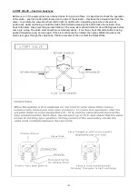
Re-setting actuator – the central knob can only be pushed back in when the valve and the actuator are exactly
in line – the valve has be rotated back to the same position it was in before the central knob was pulled out. If
this proves to be troublesome, remove actuator by un-screwing central set screw in the middle of the actuator
knob, switch on the panel, set temperature high to force the control system to rotate actuator to fully open
position, rotate valve to fully open position, install actuator and tighten screw (NOTE – ensure that the back of
the actuator locks into the locating dowel protruding from the valve body) and then tighten the central screw.
It should then be possible to push back in the central knob and so covering the orange sleeve. Once done,
return the control temperature back to the desired value.
Instantaneous Hot Water Systems
1. Installation
Lifting:
Exercise extreme caution at all times when lifting
Do not lift with the secondary shunt pump attached.
Lift from underneath if still on a base (pallet).
Lift off pallet using the lifting hole on the top at the plate heat exchanger (UKE14 only), or by attaching slings
under or through the base plate – ensure unit is steadied during manoeuvring. It is possible to lift from the top
frame bar of the heat exchanger (UKE14 only) to steady the assembly – however, do not lift from the frame bar
without using the lifting hole / from the base, as well.
It is also possible to attach a strap or sling around the top flanged connection pipe at F1 location (goes out to
the control valve) for steadying purposes only – do not lift from this point – use only to steady the unit whilst
lifting from other areas.


