-20-
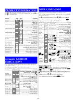
PRODUCT INFORMATION
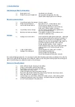
First select Product information mode from Select mode
(refer to section 2).
Press
to view each parameter. To exit from Product Information mode, hold down
and
press
to return to Select mode.
Parameter Lower
Display
Upper
Display
Description
Input type
Universal input
Option 1 module type fitted
No option fitted
Relay output
SSR drive output
Triac output
Linear DC voltage / current output
Option 2 module type fitted
As Option 1
Option 3 module type fitted
No option fitted
Relay output
SSR drive output
Linear DC voltage / current output
Transmitter power supply
Auxiliary Option A module
type fitted
No option fitted
RS485 communications
Digital Input*
Remote Setpoint Input
(basic)*
Auxiliary Option B
module type fitted
No option fitted
Remote Setpoint Input
(full)
and Digital Input 2*
Firmware type
Value displayed is firmware type number
Firmware issue
Value displayed is firmware issue number
Product Revision Level
Value displayed is Product Revision level
Date of manufacture
Mm
Manufacturing date code
(mmyy)
Serial number 1
First four digits of serial number
Serial number 2
Middle four digits of serial number
Serial number 3
Last four digits of serial number
Messages & ERROR
INDICATIONS
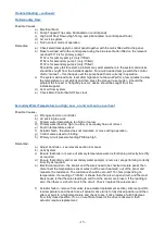
These messages indicate that an error has occurred or there is a problem with the process
variable signal or its wiring.
Caution:
Do not continue with the process until the issue is resolved.
Parameter Upper
Display
Lower
Display
Description
Instrument
parameters are in
default conditions
Configuration & Setup required. This screen is
seen at first turn on, or if hardware
configuration has been changed. Press
to
enter the Configuration Mode, next press
or
to enter the unlock code number, then
press
to proceed
Input Over Range
Normal
Process variable input > 5% over-range
Input Under Range
Normal
Process variable input > 5% under-range
Input Sensor Break
Normal
Break detected in process variable input sensor or
wiring
RSP Over Range
Normal
**
RSP input over-range
** also seen
wherever RSP
value would be
displayed
RSP Under Range
Normal
**
RSP input under-range
RSP Break
Normal
**
Break detected in RSP
input signal
Option 1 Error
Option 1 module fault
Option 2 Error
Option 2 module fault
Option 3 Error
Option 3 module fault
Option A Error
Option A module fault or RSP in both A & B
Option B Error
Option B module fault
OPERATOR MODE
This mode is entered at power on, or accessed from Select mode
(see section 2).
Note: All Configuration mode and Setup mode parameters must be set as required before
starting normal operations.
Press
to scroll through the parameters, then press
or
to set the required value.
Note: All Operator Mode parameters in Display strategy 6 are read only (see
in
configuration mode), they can only be adjusted via Setup mode.
Upper Display Lower
Display
Display Strategy and
When Visible
Description
PV Value
Active SP
Value
1 & 2
(initial screen)
PV and target value of selected SP
Local Setpoints are adjustable in
Strategy 2
PV Value
Actual SP
Value
3 & 6
(initial screen)
PV and actual value of selected SP
(e.g. ramping SP value).
Read only
PV Value
(Blank)
4
(initial screen)
Process variable only
Read only
Active SP
Value
(Blank)
5
(initial screen)
Target value of selected setpoint
only.
Read only
SP Value
1, 3, 4, 5 & 6 if digital
input is not
and
RSP not fitted
Target value of SP
Adjustable except in Strategy 6
SP1 Value
Digital input =
.
_
lit if active SP = SP1
Target value of SP1
Adjustable except in Strategy 6
SP2 Value
Digital input =
.
lit if active SP = SP2
Target value of SP2
Adjustable except in Strategy 6
Local SP
Value
RSP fitted.
or
*
lit if the
active SP =
Target value of local setpoint
Adjustable except in Strategy 6
Remote SP
Value
RSP fitted.
or
*
lit if the
active SP =
Target value of remote setpoint
Read only
,
or
RSP is fitted, digital
input is not
and
is enabled in
Setup mode
Selects local/remote active setpoint
= local SP,
= remote SP
= selection via digital input (if
configured).
Note: selecting
or
will override digital input, active
SP indication changes to
*
Adjustable except in Strategy 6
Actual SP
Value
is not blank
Actual (ramping) value of
selected SP.
Read only
Ramp Rate
enabled in
Setup mode
SP ramping rate, in units per hour
Adjustable except in Strategy 6
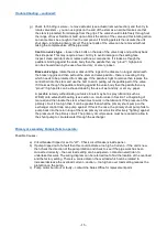
Manual Control
If
is set to
in Setup mode, manual control can be selected/de-selected by
pressing the
key in Operator mode, or by changing the status of a digital input if
or
have been configured for
in Configuration mode.
While in Manual Control mode, the
indicator will flash and the lower display will show
xxx
(where
xxx
is the current manual power level). Switching to/from manual mode is via
Bumpless Transfer. Press
or
to set the required output power.
Caution:
Manual power level is not restricted by the
power
limit
.

