


19
103536-08 - 4/18
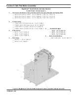
Section II: Unit-Pak Boiler Assembly (continued)
M. PROBE LWCO (HYDROLEVEL CG450,
OR, MCDONNELL-MILLER PSE801-120)
INSTALLATION.
1. Remove either Hydrolevel CG450 LWCO with
factory attached harness and Hydrolevel probe
#EL1214, or, McDonnell-Miller PSE801-120
with factory attached harness and #153875
probe from Control Carton.
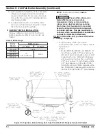
2. Install the probe into the appropriate front
section tapping. See Figure 7 “Purpose of
Tappings & Bosses”.
3. Slip LWCO with factory attached harness
over the probe and clamp in place. Note that
CG450 LWCO will be positioned right side up,
with diagnostic LED(s) on the top flange, while
PSE801 LWCO will be positioned upside down,
with diagnostic LED(s) on the bottom flange.
Connect the wire(s) between the probe and
control per manufacturer’s instructions.
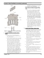
4. Pick-up the LWCO harness Molex end and
feed it into the enclosure, thru external
electrical enclosure top flange front left 7/8”
hole; then, snap-in harness BX connector
into the hole, and, plug-in Molex connector
into dedicated LWCO receptacle inside the
enclosure (middle left off transformer/relay).
See “ Control Plug-In Diagram” label attached
to inside of the enclosure cover for details
.
N. PRESSURE GAUGE AND GAUGE GLASS
INSTALLATION.
1. Remove the 6” water gauge glass set from Part
Carton.
2. Install the gauge glass using the two ½” NPT
tappings to the right of the probe LWCO. See
Figure 7 “Purpose of Tappings & Bosses”.
3. Thread the pressure gauge into 1/4” NPT
tapping of the front section. See Figure 7
“Purpose of Tappings & Bosses”. Tighten with
wrench applied to the square shank of the
gauge.
O. AQUASTAT CONTROLLER INSTALLATION
(BOILERS WITH TANKLESS HEATER ONLY).
1. On boilers with tankless heater, install the
L4006A aquastat controller well (found in Part
Carton) into ½” NPT tapping in tankless heater
plate.
2. Remove the L4006A aquastat controller with
factory attached harness from Control Carton.
Do not apply pressure to
gauge case, as this may result in inaccurate
readings.
CAUTION
3. Slip the bulb of the aquastat controller into the
well and secure the controller in place with the
set screw.
4. Feed the L4006A aquastat controller harness
end thru external electrical enclosure top
flange middle right bushed hole. See “ Control
Plug-In Diagram” label attached to inside of
the enclosure cover for details.
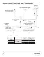
5. See Figures 21 thru 21B (whichever
applicable) for tankless heater aquastat
connection details.
6. Using needle nose pliers form hook on
harness each stripped end and wrap hooks
around screws under terminals "R" and "G" of
the R8285C Transformer-Relay; then, tighten
screws securely.
P. SAFETY VALVE AND DRAIN VALVE
INSTALLATION.
1. Remove safety valve and related piping (3/4”
NPT x 3” lg. black nipple, 3/4” NPT x 8” lg.
black nipple, ¾” NPT 90° black elbow and ¾”
NPT black coupling) from Part Carton.
2. Thread 3/4" NPT x 3” lg. black nipple into rear
section safety valve tapping, install ¾” NPT 90°
black elbow facing upward, then, thread 3/4"
NPT x 8” lg. black nipple into the elbow, and,
install ¾” NPT black coupling onto nipple end.
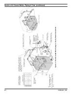
3. Thread safety valve into the ¾” NPT black
coupling. Pipe the safety valve discharge as
shown in Figure 11 “ Recommended Boiler
Piping For Gravity Return Steam Boiler” shown
in Section III of this manual. Installation of the
safety valve must be consistent with ANSI/
ASME Boiler and Pressure Vessel Code,
Section IV.
4. Remove 1-1/2" NPT x 5” lg. black nipple, 1-1/2”
x 1-1/2” x ¾” NPT black tee and drain valve
from Part Carton.
Aquastat bulb must be fully
inserted into the well.
WARNING
Safety valve discharge piping
must be piped near floor to eliminate potential
of severe burns. Do not pipe in any area where
freezing could occur. Do not install any shut-
off valves, plugs or caps.
WARNING
NOTICE
Lower rear section Tapping "H" is
used for standard condensate return on steam
boilers.
Summary of Contents for MegaSteam MST288
Page 54: ...54 103536 08 4 18 Bare Boiler Assembly Section XII Repair Parts continued...
Page 56: ...56 103536 08 4 18 Bare Boiler Assembly Section XII Repair Parts continued...
Page 58: ...58 103536 08 4 18 Jacket Assembly Section XII Repair Parts continued...
Page 62: ...62 103536 08 4 18 Beckett AFG Burner Section XII Repair Parts continued...
Page 65: ...65 103536 08 4 18...
Page 66: ...66 103536 08 4 18...
Page 67: ...67 103536 08 4 18...


