U.S. Boiler Company MegaSteam MST288 Installation, Operating And Service Instructions Download Page 10

10

103536-08 - 4/18

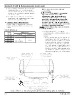
A.  CAST IRON SECTION ASSEMBLY TAPPINGS


Refer to Table 3 "Purpose of Tappings and 

Bosses" and Figure 7. 
1.  All tappings have factory installed thread 

protectors.  The thread protectors must be 

removed prior to jacket and piping installation.

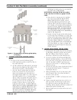
2.  Depending of installation specifics and boiler 

build ordered, some tappings (front section 

Optional Front Return, rear section Indirect 

Heater Supply and Indirect Heater Limit) may 

not be used and must be plugged before 

jacket and piping installation.  The appropriate 

size plugs for above mentioned tappings, 

as well as rear section Surface Blowoff and 

front section probe type LWCO tappings, 

are enclosed into Part Cartons (100615-01 

or 100629-01) and Control Cartons (100678-

01 and 100679-01), supplied as part of 

MegaSteam™ Unit-Pak Boiler shipment.

B.   REMOVAL  OF  CAST  IRON  SECTION/

BURNER  SWING  DOOR / SMOKE  BOX 
ASSEMBLY  FROM  SKID.

1.  Move crated Cast Iron Section/Burner 

Swing Door/Smoke Box Assembly and part 

cartons on the shipping skid as close to final 

permanent location as possible.

2.  Remove all fasteners at crate skid. Lift outside 

container. Examine the skid contents for 

damage due to shipping and handling.

3.  Remove Insulation Wrapper, Control Carton, 

Jacket Carton and Part Carton from skid and 

set aside.

4.  Instruction/Label Bag is affixed to Section 

Assembly tie rod. Remove the bag and locate 

MegaSteam™ Boiler Installation, Operating 

and Service Instruc-tion manual. READ AND 

UNDERSTAND ALL INSTRUCTIONS BEFORE 

ATTEMPTING BOILER HANDLING AND 

INSTALLATION.

5.  The Cast Iron Section/Burner Swing Door/

Smoke Box Assembly is secured to shipping 

skid with four lag screws. Remove the screws 

and discard.

6.  For manual Cast Iron Section/Burner Swing 

Door/Smoke Box Assembly removal prepare 

one piece of 4” x 4” x 16” lg. (or two pieces of 

2” x 4” x 16” lg.) and two pieces of 1” Sch. 40 

black pipe to be used as handles. Suggested 

pipe length for each handle is 72” (3-section); 

78” (4-section) and 84” (5-section).

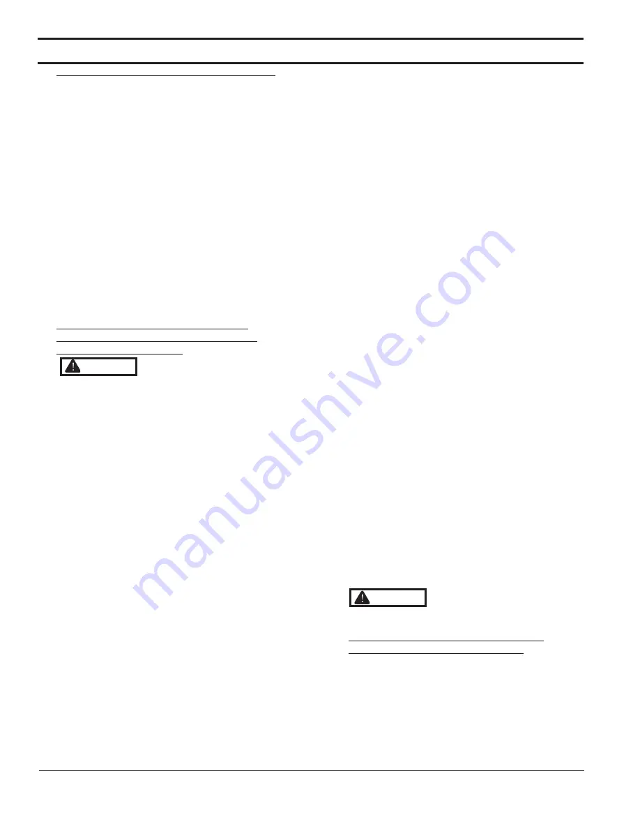
7.  Place wooden block(s) 12” from rear of skid 

as shown. See Figure 4 “ Boiler Removal from 

Skid”.

8.  Insert 1” Sch. 40 black pipe handles thru leg 

holes in front and rear section legs. Center rear 

pipe ends on wooden block(s). See Figure 4.

9.  For best leverage, the pipe handles should 

extend 48” minimum beyond front section face.

10.  Using the pipe handles, lift the Cast Iron 

Section/Burner Swing Door/Smoke Box 

Assembly until adjustable legs are elevated 

above the skid deck boards.

11.  Remove the skid from underneath the Cast 

Iron Section/Burner Swing Door/Smoke Box 

Assembly.

12.  Lower pipe handles until front adjustable legs 

touch the floor. Place wood blocks under front 

legs, if required, before lowering, to provide 

hand clearance.

13.  To lower rear of the Cast Iron Section/Burner 

Swing Door/Smoke Box Assembly tilt boiler 

slightly forward by pushing on smokebox, or, 

lift pipes protruding thru rear legs, until wooden 

block(s) can be removed (see Figure 4). Slowly 

allow the weight of boiler to tilt backward until 

rear legs rest on floor.

14.  If wood blocks were placed under front legs, 

lift pipe handles; remove the blocks and lower 

front legs to floor. Remove pipe handles.

15.  Move Cast Iron Section/Burner Swing Door/

Smoke Box Assembly to permanent position by 

sliding or walking.

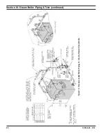
C.   PROCEDURE  TO  OPEN,  CLOSE  AND 

SECURE  BURNER  SWING  DOOR.


Throughout this manual you will be instructed to 

open and close Burner Swing Door for various 

reasons. There is a proper and improper method 

of closing and securing the door opened for front 

jacket panel installation, inspection, cleaning or 

field service. Refer to Figures 5A, 5B, 5C and 

paragraphs D “Jacket Front Panel Installation”, 

and, F “Closing/Securing Burner Swing Door” for 

details.

Section II: Unit-Pak Boiler Assembly (continued)


                      The Cast Iron Section/Burner 

Swing Door/Smoke Box Assembly has a 
substantial weight.  Insure the travel path 
to permanent location, as well as mounting 
surface at boiler permanent location, are 
structurally sound and rated to handle the 
boiler weight and water content (refer to 
Table 1A).  Otherwise, a potentially hazardous 
situation could result in death, serious injury 
and substantial property damage.


WARNING


Do not drop boiler when 

removing from skid and moving to permanent 
position.


CAUTION

Summary of Contents for MegaSteam MST288

Page 1: ...or repairs to boiler call your heating contractor When seeking information on boiler provide Boiler Model Number and Serial Number as shown on Rating Label Improper installation adjustment alteration...

Page 2: ...Automatically Fired Boilers for assembly and operations of controls and safety devices D All wiring on boilers installed in the USA shall be made in accordance with the National Electrical Code and o...

Page 3: ...ler Assembly and Steam Boiler Trim Piping Sections of this manual for details It is the responsibility of the installing contractor to see that all controls are correctly installed and are operating p...

Page 4: ...on air This boiler is supplied with controls which may cause the boiler to shut down and not re start without service If damage due to frozen pipes is a possibility the heating system should not be le...

Page 5: ...5 103536 08 4 18 Figure 1 MST288 Thru MST629 Steam Boiler with Tankless Heater Beckett Burner Shown...

Page 6: ...8 36 7 24 1 34 29 881 7 8 X 8 15 NOTE 1 Maximum Working Pressure Steam 15 PSI Boiler Model No Burner Capacity DOE Heating Capacity MBH 2 AHRI NET Ratings AFUE GPH MBH 1 Steam MBH 3 Steam Sq Ft MST288...

Page 7: ...in rooms with clearances from combustible material as listed above Listed clearances cannot be reduced for alcove or closet installations 3 For reduced clearances to combustible material protection mu...

Page 8: ...e area of 1 square inch per 4 000 BTU per hour input of all equipment in space ii Vertical ducts Minimum free area of 1 square inch per 4 000 BTU per hour input of all equipment in space Duct cross se...

Page 9: ...ntrol Carton ____ CG450 LWCO W Tankless Heater Part 100608 01 ____ PSE801 LWCO W Tankless Heater Part 100622 01 ____ CG450 LWCO L Tankless Heater Part 100680 01 ____ PSE801 LWCO L Tankless Heater Part...

Page 10: ...n See Figure 4 Boiler Removal from Skid 8 Insert 1 Sch 40 black pipe handles thru leg holes in front and rear section legs Center rear pipe ends on wooden block s See Figure 4 9 For best leverage the...

Page 11: ...11 103536 08 4 18 Figure 4 Boiler Removal from Skid Section II Unit Pak Boiler Assembly continued...

Page 12: ...panel and door mounting bracket attachment points See also Figure 7 Purpose of Tappings Bosses 2 Open Jacket Carton and locate jacket front panel has factory attached 1 fiberglass insulation See also...

Page 13: ...amber and between the left and right side 2nd and 3rd pass flueways should make an impression in door insulation to seal the chambers By design door insulation on model MST629 will have two by pass po...

Page 14: ...2nd pass flueway on left side of boiler hold baffle with word Left readable at the top Slide baffle in flueway until position tab touches fins on right side of 2nd pass flueway To install flueway baff...

Page 15: ...R PIECE OF HARDWARE 100 WITHOUT USING THE ALTERNATING METHOD DESCRIBED ABOVE See Figure 5B e Failure to follow the prescribed procedure could cause thread damage to casting and or leak at the door sea...

Page 16: ...Valve G 1 11 Condensate Return H 1 11 Optional Front Return J 1 11 Surface Blowoff Plugged K 1 11 Indirect Water Heater Supply L 14 Indirect Water Heater Limit M 4 pcs 5 16 18 Jacket Front Panel Burn...

Page 17: ...apper is vacuum packed sealed in plastic bag at the factory 2 Carefully cut the plastic bag and remove Insulation Wrapper The wrapper will expand upon removal 3 Unfold Insulation Wrapper position it o...

Page 18: ...ole located to the right of transformer relay into right side panel to secure the enclosure 8 Plug in burner harness Molex connector into dedicated burner harness receptacle inside the enclosure lower...

Page 19: ...plate 2 Remove the L4006A aquastat controller with factory attached harness from Control Carton Do not apply pressure to gauge case as this may result in inaccurate readings CAUTION 3 Slip the bulb o...

Page 20: ...full turns into tapping located at 12 00 o clock on burner swing door Section II Unit Pak Boiler Assembly continued Do not install burner without gasket CAUTION e Insert oil burner into the opening o...

Page 21: ...ed Header configuration See Table 5 for Recommended material provided or Table 7 for Dropped Header material provided for Boiler Model MST629 Note Tighten unions only after all piping is in the proper...

Page 22: ...22 103536 08 4 18 Figure 10 Recommended Boiler Piping for Gravity Return Steam Boiler Section III Steam Boiler Piping Trim continued...

Page 23: ...22 1 12 1 1 2 x 4 3 4 Nipple 101436 01 1 13 1 1 2 Wye 101437 01 1 14 1 1 2 1 1 4 Bush 806600539 2 15 1 1 4 x 22 3 16 Nipple 106711 01 1 16 1 1 4 x 3 4 x 1 1 4 Tee 806601002 2 17 1 1 4 x 9 7 8 Nipple 1...

Page 24: ...9 1 11 3 Tee 806601108 1 12 2 x 10 Nipple 806600037 1 13 2 x 13 3 8 Nipple 101441 01 1 14 2 Wye 806601124 1 15 2 1 1 2 Bush 806600517 1 16 1 1 2 x 20 5 8 Nipple 101442 01 1 17 1 1 2 x 3 4 x 1 1 2 Tee...

Page 25: ...806604022 1 13 1 1 2 x 4 3 4 Nipple 101436 01 1 14 1 1 2 Wye 101437 01 1 15 1 1 2 1 1 4 Bush 806600539 2 16 1 1 4 x 22 3 16 Nipple 106711 01 1 17 1 1 4 x 3 4 x 1 1 4 Tee 806601002 2 18 1 1 4 x 9 7 8 N...

Page 26: ...x 3 x 2 Tee 806601079 1 12 3 Tee 806601108 1 13 2 x 7 3 8 Nipple 101907 01 1 14 2 Wye 806601124 1 15 2 1 1 2 Bush 806600517 1 16 1 1 2 x 20 5 8 Nipple 101442 01 1 17 1 1 2 x 1 1 2 x 3 4 Tee 806601105...

Page 27: ...by installing it below the cold water inlet to heater to prevent lime formation in the valve Refer to Figure 16 3 FLUSHING OF HEATER All water contains some sediment which settles on the inside of the...

Page 28: ...ter Heater Piping Section IV Tankless Indirect Water Heater Piping continued Boiler Model Heater No Heater Rating GPM Pressure Drop thru Heater PSI MST288 222B 3 00 18 7 MST396 3 50 25 4 MST513 3 75 3...

Page 29: ...e SL Water Heater Piping with MegaSteam Boiler B CONNECT ALLIANCE SL INDIRECT WATER HEATER PIPING as shown in Figure 16 1 Refer to Alliance SL manual for additional information Section IV Tankless Ind...

Page 30: ...n of any new or replacement fuel burning equipment the chimney shall be inspected by a qualified installer The chimney shall be inspected for integrity as well as for proper draft and condensate contr...

Page 31: ...31 103536 08 4 18 Figure 17 Recommended Vent Pipe Arrangement and Chimney Requirements Figure 18 Proper and Improper Locations of Draft Regulator Section V Venting Air Intake Piping continued...

Page 32: ...g the draft 2 Minimum Draft at Breech Canopy The draft induced by a chimney must create at least a pressure of 0 zero inches water column w c at the pressure tapping on the canopy mounted on rear of b...

Page 33: ...e boiler F OPTIONAL AIR INTAKE PIPING INSTALLATION All air for combustion can be supplied directly to the burner from outdoors providing that the criteria for chimney vent connector and minimum stack...

Page 34: ...t so there will be free movement of room air around this control Heat Anticipator in Thermostat should be set to match the requirements of the control to which it is connected See Figures 21 thru 21B...

Page 35: ...35 103536 08 4 18 Figure 20 Wiring Diagram Hydrolevel CG450 Probe LWCO SEE FIGURE 22 FOR SCHEMATIC WIRING DIAGRAM OF APPROPRIATE BURNER AND OIL PRIMARY CONTROL OPTION Section VI Electrical continued...

Page 36: ...103536 08 4 18 Figure 21 Wiring Diagram McDonnell Miller PSE 801 Probe LWCO Section VI Electrical continued SEE FIGURE 22 FOR SCHEMATIC WIRING DIAGRAM OF APPROPRIATE BURNER AND OIL PRIMARY CONTROL OPT...

Page 37: ...37 103536 08 4 18 Section VI Electrical continued Figure 22 Wiring Diagram All Burner Options with Various Oil Primary Controls...

Page 38: ...the selected setting for proper operation of the domestic water heater if equipped with optional tankless heater BOILER SEQUENCE OF OPERATION WITH PROBE LWCO See Figure 21 When the thermostat calls fo...

Page 39: ...23 3 Fuel Oil Line Deaerator On many occasions a leaky oil delivery line can introduce air into the fuel oil supply system This often creates a rough starting condition and can create a burner lockout...

Page 40: ...s a manual shutoff valve to be located on the return line of a two pipe system Accidental closure of the return line will rupture the oil pump seals Lift H See Fig 22 Maximum Length of Tubing H R See...

Page 41: ...n Instructions contained in this manual 2 Confirm all electrical water and oil supplies are turned off at the source and that the vent is clear from obstructions B FILL HEATING SYSTEM WITH WATER CLEAN...

Page 42: ...n reasons the burner ceases to fire and the reset button on the primary control has tripped the burner has experienced ignition failure H CHECK FOR CLEAN CUT OFF OF BURNER 1 AIR IN THE OIL LINE betwee...

Page 43: ...lR7284modelshaveinternal TTConfigured ON parameters set to ON f The R7284 has an LCD display and simply displays lockout and flame status on it g Cad Cell Resistance Check For proper operation it is i...

Page 44: ...itch Close line switch to boiler If burner starts and runs beyond safety switch cut off time cell is good If not install new cell Close hand valve in oil supply line Failure occurs device enters Recyc...

Page 45: ...othing 3 Gloves 4 Eye Protection Take steps to assure adequate ventilation Wash all exposed body areas gently with soap and water after contact Wash work clothes separately from other laundry and rins...

Page 46: ...in the boiler to a boil to drive off free oxygen q WARNING BEFORE RETURNING BOILER TO SERVICE Follow the low water cut off check out procedure in Section VIII Paragraph I No 4 B BOILER AND SYSTEM CLE...

Page 47: ...ommended boilout compound Remove safety valve from boiler and pour this solution into boiler then reinstall safety valve iii Turn on oil burner and keep operating while feeding water to boiler slowly...

Page 48: ...arranty does not cover oxygen corrosion and sediment related damage Clearly it is in everyone s best interest to prevent this type of failure You can do your part by ensuring that your system is leak...

Page 49: ...e combustion chamber and smoke box B CLEAN THE COMBUSTION CHAMBER Use a wire or fiber bristle brush to clean the surfaces of the combustion chamber Vacuum all of the loose debris in the bottom of the...

Page 50: ...uate chimney The interior of the chimney flue must be inspected and cleaned before the start of the heating season and should be inspected periodically throughout the heating season for any obstructio...

Page 51: ...he slots become in the nozzle and the more prone to plugging it becomes with the same amount of dirt 7 WATER Water in the fuel in large amounts will stall the fuel pump Water in the fuel in smaller am...

Page 52: ...zzle clogged d Airflow too high e Ignitor module defective f CAD cell defective g Oil valve stuck open or closed Note The Safety Monitoring Circuit SMC is designed to provide lockout in the event of a...

Page 53: ...esale distributor Should you require assistance in locating a U S Boiler Company Distributor in your area or have questions regarding the availability of U S Boiler Company products or repair parts pl...

Page 54: ...54 103536 08 4 18 Bare Boiler Assembly Section XII Repair Parts continued...

Page 55: ...F Hex Nut 5 16 18 Serrated Flange Plated 80860443 4 4 4 4 1G Hinge Bracket 100014 01 1 1 1 1 1H 5 16 18 x 3 4 Lg Cap Screw Plated Hinge Bracket 80861340 2 2 2 2 Mount Burner 3 3 3 3 1J Cast Iron Burne...

Page 56: ...56 103536 08 4 18 Bare Boiler Assembly Section XII Repair Parts continued...

Page 57: ...Plated 80860611 2 2 2 2 1Z Cap Screw 5 16 18 x 7 8 Lg Plated 80861371 6 6 6 6 1AA Cast Iron Clean Cut Cover only 100104 01 2 2 2 2 1BB 1 2 Dia Rope Gasket Clean Cut Cover 100095 01 2 2 2 2 1CC 222B H...

Page 58: ...58 103536 08 4 18 Jacket Assembly Section XII Repair Parts continued...

Page 59: ...0614 04 1 100614 05 1 2K Jacket Left Side Panel 3 Section 100581 03 1 1 Jacket Left Side Panel 4 Section 100581 04 1 Jacket Left Side Panel 5 Section 100581 05 1 2L Jacket Right Side Panel 3 Section 1...

Page 60: ...60 103536 08 4 18 MST288 Thru MST629 Steam Boilers Trim and Controls Section XII Repair Parts continued...

Page 61: ...3 4 NPT 15 PSI Conbraco 13 511 08 81660530 1 1 1 1 3M Gauge Glass Set 6 Conbraco 20 104 10 8056091 1 1 1 1 3P Nipple 1 1 2 NPT x 5 Lg 808600060 1 1 1 1 3Q Tee 1 1 2 x 1 1 2 x 3 4 806601105 1 1 1 1 3R...

Page 62: ...62 103536 08 4 18 Beckett AFG Burner Section XII Repair Parts continued...

Page 63: ...amp Screw 4219 4219 4219 4219 Electrode Insulator Assembly 5780 5780 5780 5780 Support Spacer Assembly 5992 5992 5992 5992 Escutcheon Plate Adjusting Plate Assembly 5941 5941 5941 5941 Head 5913 5913...

Page 64: ...1 65 V1 3 10 3 1 25 x 60B Hago 180 11 5 2nd 52 0 0 0 050 0 030 Notes 1 MST288 at 0 75 GPH firing rate utilizes a low fire baffle 2 The increased stack temperature with the baffles removed is an appro...

Page 65: ...65 103536 08 4 18...

Page 66: ...66 103536 08 4 18...

Page 67: ...67 103536 08 4 18...

Page 68: ...68 103536 08 4 18 U S Boiler Company Inc P O Box 3020 Lancaster PA 17604 1 888 432 8887 www usboiler net...

Reviews: