


18
103536-08 - 4/18
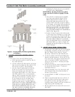
over four #8 x ½” shoulder sheet metal screws,
previously installed at Front and Rear Jacket
Panel side flanges, so teardrop cutouts in
the side panel inside flanges engage all four
screws simultaneously.
7. Slide the panel downwards to lock all screws
securely.
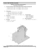
8. Pick up Top Jacket Panel from Jacket Carton.
9. Place the panel between side panels upper
inside flanges and slide it forward, until top
panel front flange U-bend locks over front
panel top flange, and, top panel rear flange is
positioned over rear jacket panel.
10. Locate/remove two #8 x ½” sheet metal screws
from Hardware Bag.
11. Install both screws into top panel rear flange to
secure the top panel to rear jacket panel.
K. EXTERNAL ELECTRICAL ENCLOSURE
MOUNTING.
1. Remove two #8 x ½” shoulder sheet metal
screws and one #8 x ½” sheet metal screw
from Hardware Bag.
2. Install both #8 x ½” shoulder sheet metal
screws into Right Side Jacket Panel, at two
upper corners of the panel front cutout.
3. Locate and remove External Electrical
Enclosure assembly from Control Carton.
4. Remove the enclosure cover and set aside.
5. Pick Molex connector end of Burner Harness
and feed it inside the enclosure, thru bushed
hole at enclosure lower left corner, next to
transformer/relay.
6. Place the enclosure over installed shoulder
sheet metal screws, so teardrop cutouts in
the enclosure base engage both screws
simultaneously, then, slide the enclosure
downwards to lock it in place.
7. Install #8 x ½” sheet metal screw thru
enclosure base lower hole, located to the right
of transformer/relay, into right side panel to
secure the enclosure.
8. Plug-in burner harness Molex connector into
dedicated burner harness receptacle inside
the enclosure (lower left off transformer/relay).
See “ Control Plug-In Diagram” label attached
to inside of the enclosure cover for details.
9. Do not install the enclosure cover yet; proceed
to control installation.
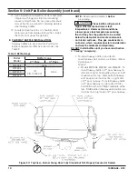
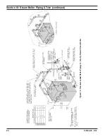
Figure 8: Pressure Limit Installation
L. TRIM AND CONTROLS INSTALLATION.
Pressure Limit Installation.
1. Locate and remove L404F Pressure Limit with
factory attached harness from Control Carton.
2. Locate and remove 1/4" NPT x 1-7/8" x 4 x 90°
syphon enclosed in Part Carton.
3. Review and locate pressure limit tapping
on front section. See Table 3 “ Purpose of
Tappings & Bosses” and Figure 7.
4. Thread 1-7/8" lg. syphon-threaded short end
into the bottom of Pressure Limit with factory
attached harness. Do not tighten the syphon
by holding the limit case; apply a wrench to the
brass hex below the case.
5. Thread ¼" NPT x 4" lg. syphon-threaded long
end into pressure limit tapping on front section.
See Figure 8 "Pressure Limit Installation.
Section II: Unit-Pak Boiler Assembly (continued)
6. L404F pressure limit does not require leveling.
The pressure limit final orientation must be
parallel to boiler front, having the harness on
the right side.
7. Pick-up the pressure limit harness Molex end
and feed it into the enclosure, thru top flange
rear left 7/8” hole; then, snap-in harness BX
connector into the hole, and, plug Molex
connector into dedicated pressure limit
receptacle inside the enclosure (upper left
off transformer/relay). See “ Control Plug-
In Diagram” label attached to inside of the
enclosure cover for details.
Summary of Contents for MegaSteam MST288
Page 54: ...54 103536 08 4 18 Bare Boiler Assembly Section XII Repair Parts continued...
Page 56: ...56 103536 08 4 18 Bare Boiler Assembly Section XII Repair Parts continued...
Page 58: ...58 103536 08 4 18 Jacket Assembly Section XII Repair Parts continued...
Page 62: ...62 103536 08 4 18 Beckett AFG Burner Section XII Repair Parts continued...
Page 65: ...65 103536 08 4 18...
Page 66: ...66 103536 08 4 18...
Page 67: ...67 103536 08 4 18...


