background image

8

ADA15IM

ADA SERIES

Ice Maker Maintenance

Ice Cube Thickness Adjustment

Interval - As Required

On ice maker equipped models, the cube size may be 
adjusted by changing the amount of water injected into 
the ice maker assembly as follows:

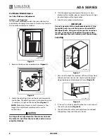
Figure 5

1. Remove the ice maker assembly cover 

(Figure 6)

.

Figure 6

2. Locate the adjusting screw on the ice maker assembly 

control box. The adjusting screw is just below the minus 
(-) and plus (+) signs on the control box 

(Figure 7)

.

NOTE:

 Make adjustments in small increments. Too 

large of an adjustment could cause the unit to 
malfunction.

CAUTION

Too large of an adjustment to the screw can cause 
the water to overflow the ice maker and can cause 
property damage.

3. Turn the adjusting screw toward the minus (-) sign 

(clockwise) for smaller cubes or toward the plus (+) sign 
(counterclockwise) for larger cubes.

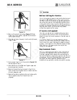
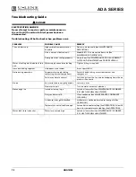
4. Install the ice maker assembly cover.

IMPORTANT

IMPORTANT

Use only genuine U-Line replacement parts. U-Line 
ice maker parts are not the same as standard FSP 
Whirlpool parts. Using non U-Line parts can reduce 
ice rate, cause water to overflow from ice maker 
mold, damage the unit, and may void the warranty.

Leveling

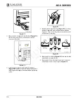
Figure 7

1. Use a level to check the levelness of the unit from front 

to back and from side to side. Level should be placed 
along top edge and side edge as shown

 (Figure 8)

.

Figure 8

2. If the unit is not level, adjust the feet on the corners of 

the unit as necessary 

(Figure 9)

.

3. Check the levelness after each adjustment and repeat 

the previous steps until the unit is level.

ULIN_0275_A

ULIN_0056_A

Place 
level
here

ULIN_0043_A

1

ULIN_0044_A

Summary of Contents for ADA SERIES

Page 1: ...Use and Care Guide ADA15IM A D A S E R I E S Ice Maker Model ADA15IM...

Page 2: ...this guide is your U Line Corporation Limited Warranty Register the product and the original purchase date to validate your warranty Included in the package containing this guide is a Warranty Regist...

Page 3: ...duct Features 3 Model ADA15IM Ice Maker 3 Operation 3 Initial Startup 3 Temperature Control 3 Ice Maker 4 Normal Operating Sounds 4 Outdoor Marine and RV Usage 5 Storage Vacation Moving 5 Product Disp...

Page 4: ...throw away your old refrigerator or freezer take off the doors and leave shelves in place so that children may not easily climb inside WARNING SHOCK HAZARD Electrical Grounding Required Never attempt...

Page 5: ...ubject to change without notice Figure 1 IMPORTANT IMPORTANT Proper air flow Figure 1 is required for your unit to operate at its highest efficiently A grille located in the base of the unit must not...

Page 6: ...part cubes If the ice maker is not used regularly the ice bucket should be emptied periodically to ensure fresh cubes It is normal for cubes to appear cloudy This is caused by air being trapped in the...

Page 7: ...ect the water valve inlet and outlet lines and allow them to drain completely 5 Reconnect power to the unit and allow it to run for one hour minimum until any remaining ice has been ejected from the i...

Page 8: ...leaners that are not specifically intended for stainless steel on stainless steel surfaces this includes glass tile and counter cleaners If any surface discoloring or rusting appears clean it quickly...

Page 9: ...ace a towel or other absorbent material on bottom of unit Figure 4 1 4 If you would like place warm water inside ice bucket Then place ice bucket back into unit and close door 5 After approximately on...

Page 10: ...3 Turn the adjusting screw toward the minus sign clockwise for smaller cubes or toward the plus sign counterclockwise for larger cubes 4 Install the ice maker assembly cover IMPORTANT IMPORTANT Use on...

Page 11: ...igure 9 1 Loosen do not remove top Figure 10 and bottom hinge screws 2 Align door squarely with cabinet 3 Make sure gasket is firmly in contact with cabinet all the way around the door no gaps 4 Tight...

Page 12: ...cate plastic spacer bushing Figure 15 on bottom of door to opposite side and place door on bottom hinge pin Clean out bushing hole in door bottom with a screwdriver if necessary Figure 15 8 Remove pla...

Page 13: ...e will assist you in quickly identifying common problems and provide information on possible causes and remedies Most often this will resolve the problem without the need to call for service If Servic...

Page 14: ...use of cubes Break apart cubes Noise during operation Copper water supply tubing contacting internal components Carefully bend tubing away from cabinet and components Certain sounds are normal Soft so...

Page 15: ...s Laboratory UL as noted in the U Line Product Catalog U Line s website and or on the serial tag located inside the product Exposure to temperatures below freezing may cause damage to the product Dama...

Page 16: ...s are available for view ing and download on line at www u line com specs SERVICE INFORMATION If you have a problem with this appliance your use and care guide has troubleshhoting information to help...

Reviews: