48
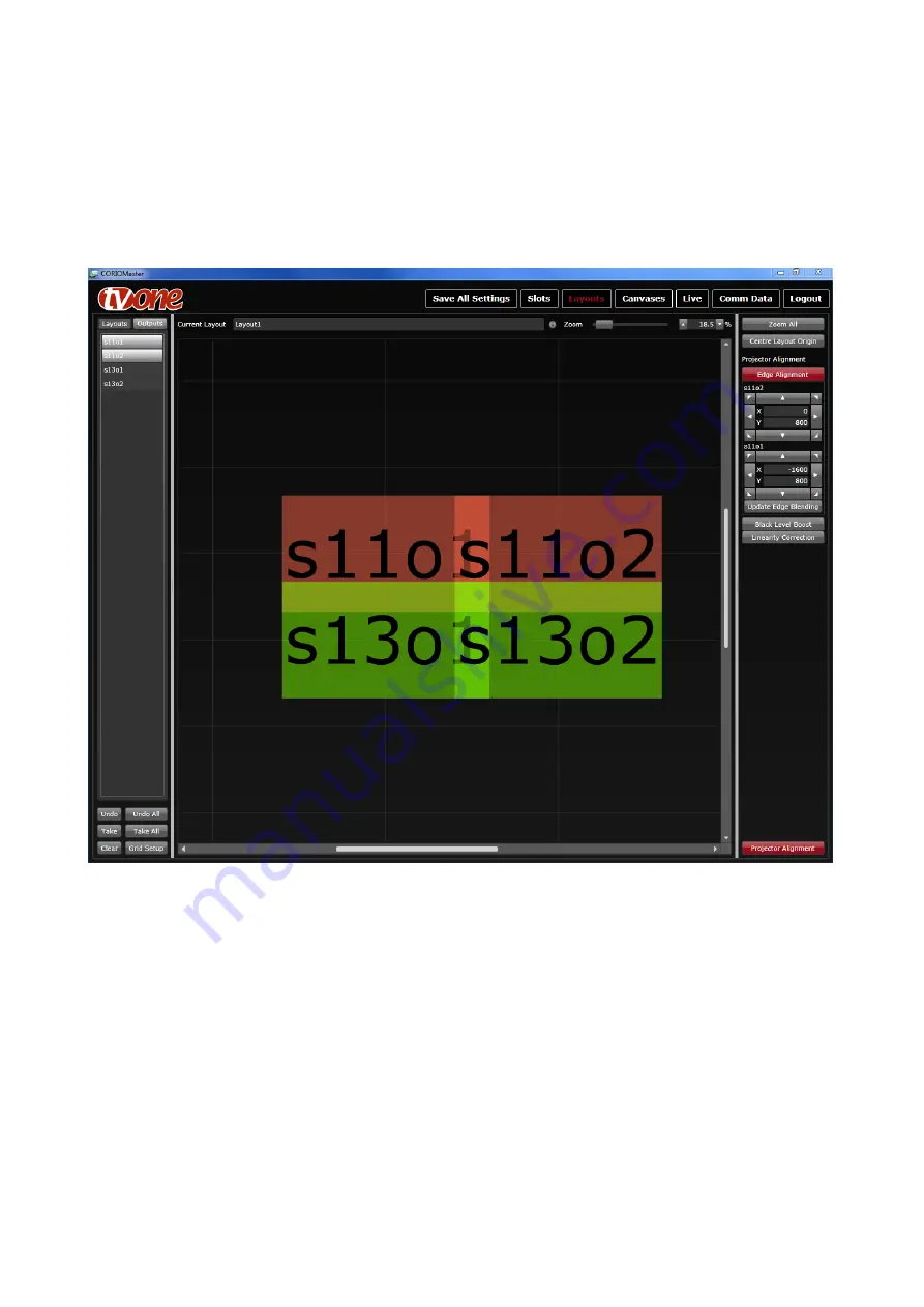
The user should now use these lines to correct the projectors alignment by mechanical
positioning or lens control on each projector. The aim is to make sure the size of the
projections are the same by use of the green boxes and that the red and green lines are
both parallel with each other and are projecting on top of each other to produce a single
yellow line.
The user is able to produce a small amount of adjustment of the red lines in software by
“nudging” the position of the outputs on the right-hand side. However this should only be
used for minor corrections.
11.3.2 S-Curve Correction
Once all the projectors have been aligned the next stage is to correct for and brightness
non linearity at the blends.
The user should now feed in a flat brightness image onto the whole layout. (Currently this
will require an external video source, and setting up a canvas to use this layout and place
a large single window of this source to cover the whole layout)


