24
8.3 V-BELT DRIVE
Before attempting to tension the V-belt drive it is imperative that the
sheaves be properly aligned. V-belts should be replaced and the sheaves
should be positioned so as to allow the belt to be placed in the grooves
without rolling them onto the sheaves.
The following tensioning steps can be safely followed for all belt types,
cross sections, number of belts per drive, or type of construction:
1. With belts properly in their grooves adjust the sheaves until all slack
has been taken up.
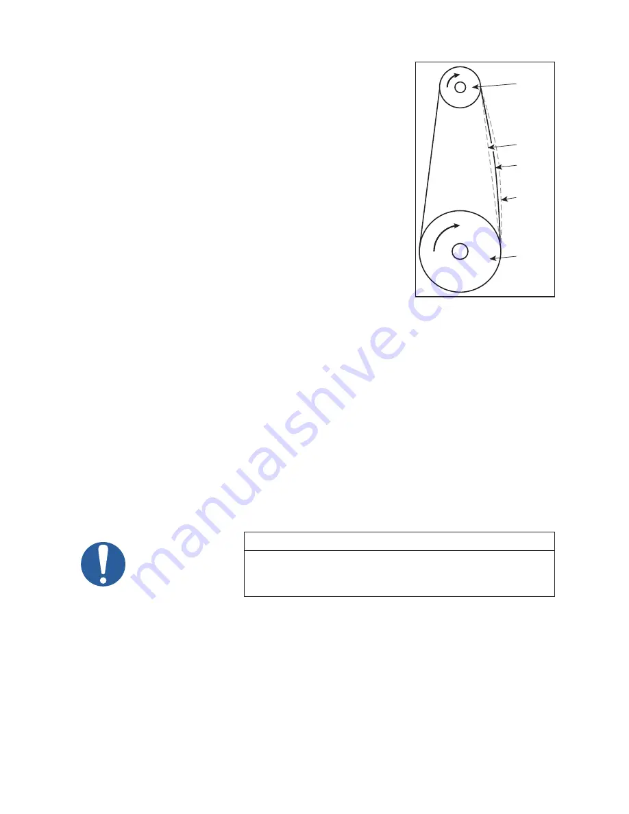
2. Start the drive and continue to tension the V-belt(s) until only a slight
bow on the slack side of the drive appears while operating under load
conditions as shown in Figure 10.
3. After 24 to 48 hours of operation for the belts will seat themselves
in the sheave grooves. Further tensioning is then necessary as
described in step 2.
4. The belts should not slip if they are correctly adjusted and the correct
starting procedure is used. A screeching noise at start-up may
indicate the belts are too loose. Belt dressing should not be used on
V-belts. Sheaves and V-belts should remain free of oil and grease.
Tension should be removed from belts if the drive is to be inactive for
an extended priod of time.
8.4 DISASSEMBLY
The following steps are for complete disassembly of the pump, however the pump should be disassembled
only to the extent necessary for servicing. Refer to the illustrations and parts list as needed. Note that the
open head is the head through which the shaft extends, and closed head is the head on which the oil pump
is mounted.
1. Disconnect all manifolding, water lines, and electrical connections and drain the oil.
2. Remove the belt guard and belts.
3. Remove the oil lines from both ends.
4. Remove the motor from the top of the pump.
5. Remove the pump sheave and drive key.
6. Remove the oil sight gauge from the separator cover. Remove the inspection cover from the separator.
7. Remove the separator housing and gasket from the cylinder.
NOTE
The separator housing has threaded holes to receive eye bolts for lifting
the pump. When the separator housing is removed, do not attempt to lift
the pump cylinder by using the gas ballast or oil drain piping to attach or
support rigging for hoisting the cylinder.
8. Unscrew the air/oil separator assembly. Remove the valve cover from the cylinder.
9. Remove the discharge valves. If valves are disassembled, careful note should be made for proper
reassembly.
10. Remove bearing retaining plate.
11. Unscrew the retainer nut from the shaft.
12. Remove the cap screws from the housing.
13. Remove the bearing, housing and stationary parts of the shaft seal.
14. Remove the rotating part of the shaft seal.
15. Remove the oil pump and housing from the closed head. Remove the closed head using two securing
bolts as jackscrews to break the seal between head and cylinder after all securing screws are removed.
Press the sleeve bearing from the head.
16. Withdraw the slide-pin, piston, cam and slidepin spacer.
PUMP
MOTOR
TOO
TIGHT
SLIGHT
BOW
TOO
LOOSE
Figure 10 - V-Belt Tensioning
Summary of Contents for KINNEY 850D
Page 29: ...29 NOTES ...
Page 35: ...35 NOTES ...


