


Dealer Instructions 11
ing on pallet (Photo 10). Use the two small pal-
lets, shipped with unit, as chocks for the wheels
on the wheel carriage (Photo 11). This will keep
the frame from rolling off the pallet and cause-
serious injury or death. While the frame is rest-
ing on the pallet, relocate the sling from its cur-
rent location to the main bar (6x4 tube) on front
of frame (Photo 12). This will allow you to attach
the leveling assembly without interference in a
later step. Once sling has been relocated, con-
nect to overhead hoist and raise hoist until
slack has been removed from sling.
When completing this portion of the assembly
process, be careful handling the large parts.
The components are heavy and dropping them
could lead to serious injury or death.
Keep slight upward pressure on front of frame
and cut bands connecting the rear of frame to
the pallet (Photo 13). When all bands have
been cut, lower the frame to the tongue lying on
the ground. Down pressure may need to be
applied to frame in order for the frame to come
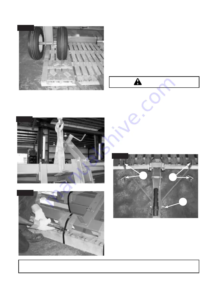
down. Connecting the tongue to the frame will
be the next step in assembly. The two 7/8” x 6
½” Gr. 5 bolts removed from an earlier step
(Photo 4) will be needed for this process. Once
frame has been lowered to the pallet, remove
the two 7/8” x 3 ½” Gr. 5 bolts from the tongue
Bolt Torque Chart (Page 45) for proper torque
information.
Before unit can be lowered to pallet, remove the
bracing the wheel carriage was resting on when
shipped (Photo 9). When bracing has been
removed, lower frame so that wheels are rest-
Photo 11
Photo 12
WARNING
Photo 13
Photo 14
2
1
1
Summary of Contents for MVT1710
Page 1: ...MVT17_16154_06 2018 VT1710 VT1713 VT1712 VT1715 VERTICAL TILLAGE O P E R A T O R S M A N U A L...
Page 23: ...Dealer Instructions 20...
Page 24: ...Operation 21 45 3 8 3 8...
Page 29: ...Owner Service 26...
Page 31: ...Assembly Schematic 28 DUAL WHEELS ARE STANDARD ON ALL MODELS MVT Assembly Schematic Figure 3...
Page 48: ...Bolt and Torque Chart 45 MVT Series gang bolt torquee 350lbs ft then tighten nut clockwise 180...
Page 49: ...Notes 46 Notes...
Page 50: ...2018 Monroe Tufline Manufacturing Inc All Rights Reserved PART NO 16154...