Maintenance
45
14. Mark the position of the motor bracket to the roller so that the
hydraulic motor can be put back into the same position it was
in before the removal.
In this way, you will prevent the hydraulic motor from being
inserted out of position by 90° or 180°.
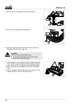
15. Pull out the motor bracket (1) together with the hydraulic motor
(2) out of the roller shaft.
000088
1
2
NOTE!
If the hydraulic motor is not in its original position, the
length of the hydraulic hoses is not sufficient.
000089
1
3
2
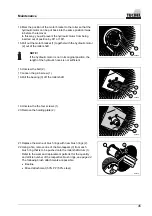
16. Unscrew the bolt (2).
17. Loosen the grub screw (1).
18. Pull the bearing (3) off the roller shaft.
000090
1
2
19. Unscrew the the four screws (1).
20. Remove the holding plate (2).
000113
3
2
1
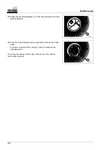
21. Replace the worn-out brush rings with new brush rings (2).
22. Using a file, remove one of the two tappets (3) from each
brush ring that is to be pushed onto the roller shaft drum (1).
Refer to the wear and replacement parts list for the quantity
and article number of the respective brush rings,
see page 42
.
The following brush attachments are possible:
•
Beeline
•
Mixed attachment (50% PP / 50% steel)
Summary of Contents for Big
Page 1: ...1 0 2008 02 01 Instruction manual 000050 Sweeper shovel attachment ...
Page 54: ......
Page 55: ......


