


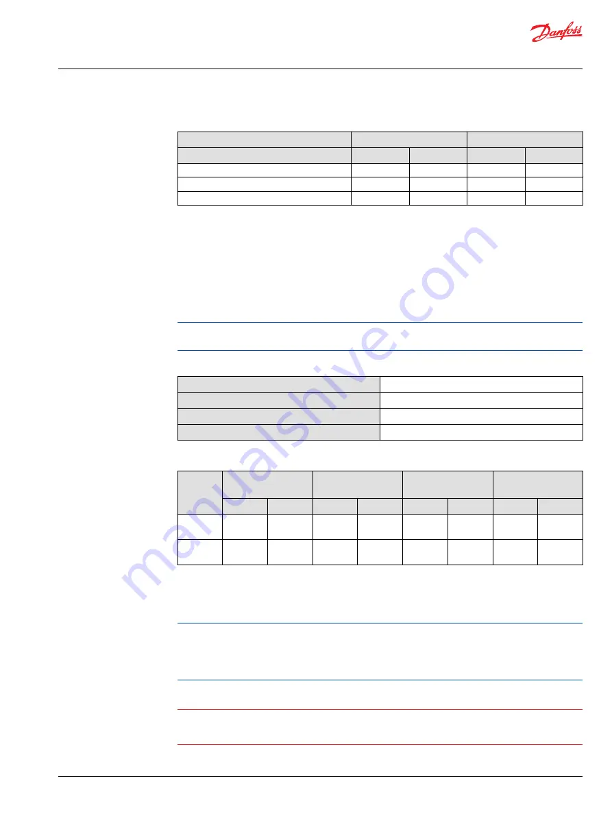
Pump output flow direction vs. control signal
Shaft rotation
CW
CCW
Coil energized
*
C1
C2
C1
C2
Port A
out
in
in
out
Port B
in
out
out
in
Servo port pressurized
M4
M5
M4
M5
*
For coil location see Installation drawings.
Control response
MP1 controls are available with optional control passage orifices to assist in matching the rate of
swashplate response to the application requirements (e.g. in the event of electrical failure). The time
required for the pump output flow to change from zero to full flow (acceleration) or full flow to zero
(deceleration) is a net function of spool porting, orifices, and charge pressure. A swashplate response
table is available for each frame indicating available swashplate response times. Testing should be
conducted to verify the proper orifice selection for the desired response.
MP1 pumps are limited in mechanical orificing combinations. Mechanical servo orifices are to be used
only for fail-safe return to neutral in the event of an electrical failure.
Typical response times shown below at the following conditions:
Δp
250 bar [3626 psi]
Viscosity and temperature
30 mm²/s [141 SUS] and 50 °C [122 °F]
Charge pressure
20 bar [290 psi]
Speed
1800 min
-1
(rpm)
Response time, EDC
Stroking
direction
0.8 mm [0.03 in]
orifice
1.0 mm [0.04 in]
orifice
1.3 mm [0.05 in]
orifice
No orifice
28/32
38/45
28/32
38/45
28/32
38/45
28/32
38/45
Neutral to
full flow
1.3 s
2.1 s
0.9 s
1.3 s
0.6 s
0.9 s
0.4 s
0.6 s
Full flow to
neutral
1.0 s
1.5 s
0.7 s
0.9 s
0.4 s
0.6 s
0.2 s
0.3 s
Manual Over Ride (MOR)
Electro-hydraulic controls are available with a Manual Over Ride (MOR) either standard or as an option for
temporary actuation of the control to aid in diagnostics.
Unintended MOR operation will cause the pump to go into stroke. The vehicle or device must always be
in a safe condition (i.e. vehicle lifted off the ground) when using the MOR function. The MOR plunger has
a 4 mm diameter and must be manually depressed to be engaged. Depressing the plunger mechanically
moves the control spool which allows the pump to go on stroke. The MOR should be engaged
anticipating a full stroke response from the pump.
W
Warning
An o-ring seal is used to seal the MOR plunger where initial actuation of the function will require a force
of 45 N to engage the plunger. Additional actuations typically require less force to engage the MOR
plunger. Proportional control of the pump using the MOR should not be expected.
Refer to the control flow table in the size specific technical information for the relationship of solenoid to
direction of flow.
Service Manual
MP1
Operation
©
Danfoss | July 2017
AX00000244en-US0103 | 15
Summary of Contents for DP20-4H
Page 11: ......
Page 12: ......
Page 26: ......
Page 27: ......
Page 28: ......
Page 29: ......
Page 30: ......
Page 31: ......
Page 32: ......
Page 33: ......
Page 34: ......
Page 35: ...Service Manual Variable Displacement Pumps MP1 powersolutions danfoss com ...
Page 93: ...Service Manual MP1 Danfoss July 2017 AX00000244en US0103 59 ...
Page 94: ...Service Manual MP1 60 Danfoss July 2017 AX00000244en US0103 ...
Page 95: ...Service Manual MP1 Danfoss July 2017 AX00000244en US0103 61 ...
Page 110: ......
Page 111: ......
Page 112: ......
Page 113: ......
Page 115: ......
Page 154: ......
Page 156: ...www dexteraxle com OPERATION MAINTENANCE SERVICE MANUAL 600 8 000 lb Axles Related Components ...
Page 238: ...Service Record Date Service Performed Mileage ...
Page 239: ...Service Record Date Service Performed Mileage ...
Page 240: ...Service Record Date Service Performed Mileage ...


