background image

10

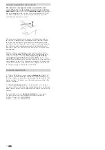
Exhaust gas cowl

The heater is only approved when used with a roof cowl. 
This must be installed vertically or with no more than a 
15 degree slope!

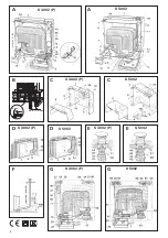
Fig. F:

 Position the roof cowl so that the duct (minimum 

length 1.5 m, maximum length 3 m) can be routed direct from 
the heater unit, sloping upward all the way to the cowl. A 
1.5 metre long duct must reach a height of at least 1 metre. 
The remain der of the duct to the roof cowl must be installed 
more or less vertically.

Trumatic S 3002 (P)

Fig. E:

 Cut out an opening with a Ø of 60 mm at a centre dis-

tance of at least 55 mm from the side walls.

Trumatic S 5002

1. Fig. E:

 Cut out an opening with a Ø of 70 mm at a centre 

distance of at least 60 mm from the side walls. 

2 Fig. E:

 In the case of a double-skin roof, line the cavity with 

wood or slide in a rolled circular sheet metal strip (20) of about 
220 mm in length and 1 mm in thick ness, to stiffen the roof so 
that when the screws are tightened it does not warp and stays 
weatherproof.

3. Fig. E:

 Push the cowl through the roof from above and 

fasten it on the inside with screw ring (21). Next, secure the 
screw ring (21) with a screw (44).

Use the enclosed rubber sealing ring without further sealing 
materials.

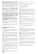
Exhaust duct

For the Trumatic S, only the Truma stainless-steel waste gas 
pipe AE 3 or AE 5 with the Truma pipe sheath UR or UR 5 (APP) 
may be used, since the devices have only been tested and ap-
proved in conjunction with these pipes.

Length of exhaust duct: min. 1.5 m, max. 3 m!

Fitting and bending the stainless steel duct and stretch-
ing open the O-ring are made considerably easier by using 
“Biege-Boy“ (part no. 30030-33000).

1. Connecting the exhaust duct to the heater: 

Slide sealing plate (22) about 3 cm onto the exhaust duct 
(with the claw pointing towards the heater exhaust outlet). 
Slide on pressure ring (25). Stretch open O-Ring (23) and 
carefully pass it over the cut edge of the duct. Then plug the 
exhaust duct into the exhaust outlet as far as the stop.

Slide the O-ring, pressure ring and sealing plate to the exhaust 
outlet. Twist on sealing plate (22) and fasten it securely by 
tightening screw (24).

A new O-ring (23) must be fitted each time the 
exhaust duct is dismantled.

2. Slide insulating duct (41) onto the exhaust duct (it must 
reach from the cowl to the rear wall of the installation box, 
refer to fig. E + D).

3. Fig. D + E:

 Take the ducting up the wall with as few bends 

as possible. Slide exhaust gas duct (40) into the cowl as far as 
the stop and secure with self-tapping screw (28).

The flue gas pipe (40) with insulating duct (41) 
must be ascending along its entire length and se-

curely and permanently installed 

using several clamps 

(42),

 since otherwise a water pocket may form that will 

prevent the flue gas from exiting freely.

Gas connection

Fig. A (e):

 The gas supply’s operating pressure (30 mbar) 

must be the same as the unit´s operating pressure (see type 
plate).

Fig. G:

 The gas supply pipe (32) must be connected using a 

cutting ring screw fitting with an outer diameter of 8 mm at 
the connecting piece (33).

The gas connection fitting on the heating appli-
ance must not be bent!

 When tightening the connec-

tion nipple, hold it carefully in place with a second wrench!

Route the ducting in such a way that the heater can be re-
moved for servicing work.

Make sure the gas lines are free of dirt, chips and such prior 
to connecting!

A special duct for internal gas connection is available on re-
quest. It is screwed onto gas connection fitting (33) with an 
elbow.

The gas system must accord with the technical and adminis-
trative provisions of the individual country of use (in Europe, 
for example, EN 1949 for motor vehicles).

National regulations and rulings (in Germany, for example, 
the DVGW worksheet G 607 for motor vehicles) must be 
respected.

Heater casing

1. Fig. G:

 Push the handle connector (26), the piezo pressure 

igniter (27) if applicable, and the integrated operating element 
(51) for the Trumavent TEB fan into the cut-outs (take care to 
respect right-hand or left-hand installation!). Close off any un-
occupied cut-outs with the closure cover (50).

For Trumatic S 3002 P only 

Plug the earthing cable (34) to the pressure igniter (27) and 
the earth contact (37) on the casing.

2. Press type plate (52) into the observation window opening 
(note right-handed or left-handed installation!).

3. With integrated control panel (51) plug connecting cable 
(53) of the Trumavent fan TEB into the control panel. Bend 
back strap (54) on the installation box and insert connecting 
cable (53).

For Trumatic S 3002 P only

Slide flat connector of ignition cable (38) on the connection 
(36) on the piezo ignitor (27) and slide on insulation (43 – refer 
to fig. A).

Summary of Contents for S 3002

Page 1: ...40 Einbauanweisung Seite 3 Installation instructions Page 8 Istruzioni di montaggio Pagina 18 Inbouwhandleiding Pagina 23 Monteringsanvisning Side 28 Instructions de montage Page 13 Instrucciones de montaje Página 33 Komfort für unterwegs ...

Page 2: ...2 2 S 3002 P E F A A S 3002 P S 5002 S 3002 P C G S 3002 P G S 5002 S 3002 P D S 5002 D S 5002 C E S 5002 ca 5 10 cm 2 cm B ...

Page 3: ...3 2603 Die Heizung erfüllt die EMV Richtlinie 2004 108 EG sowie die Altfahrzeug Richtlinie 2000 53 EG Vorschriften Zum Erlöschen von Gewährleistungs und Garantieansprüchen sowie zum Ausschluss von Haftungsansprüchen führen insbesondere Veränderungen am Gerät einschließlich Zubehörteilen Veränderungen an der Abgasführung und am Kamin Verwendung von anderen als Truma Originalteilen als Ersatz und Zu...

Page 4: ... 7 und Kapillarrohr 10 dürfen auf keinen Fall am Wärmetauscher bzw an der Heizungsverkleidung anliegen Bild B Wird die Heizung auf einen Sockel Doppelboden oder Ähnlichem montiert muss zwingend die Ansaugver längerung Art Nr 30030 04800 Länge 50 cm verwendet werden Die Ansaugverlängerung muss frei im Luftstrom ca 5 bis 10 cm unter der tiefsten Stelle des Fahrzeuges heraus ragen Länge bei Bedarf kü...

Page 5: ...Verwendung des Biege Boys Art Nr 30030 33000 1 Abgasrohr an die Heizung anschließen Dichtplatte 22 etwa 3 cm auf das Abgasrohr schieben Kralle zeigt zum Abgasstutzen der Heizung Druckring 25 aufschie ben O Ring 23 durch Ausweiten vorsichtig über die Rohr schnittkante führen und Abgasrohr bis auf Anschlag in den Abgasstutzen stecken O Ring Druckring und Dichtplatte an den Abgasstutzen her anschiebe...

Page 6: ...1 V und 15 V liefern und die Wechselspannungs welligkeit 1 2 Vss beträgt Für die unterschiedlichen Anwen dungsfälle empfehlen wir die Ladeautomaten von Truma Bitte fragen Sie Ihren Händler Andere Ladegeräte nur mit einer 12 V Batterie als Puffer verwenden Die Zuleitung 12 V am Boden nach hinten durchführen und mittels der beiliegenden Klammer am Heizungssockel fixieren 12V Bedienteil Die Verkleidu...

Page 7: ...ahrt Die Flamme kann dadurch zurück brennen und Schäden an der Heizung und am Fahrzeug verursachen In diesen Fällen müssen weitere Kaminverlän gerungen verwendet werden so dass der Kaminaufsatz min destens 10 cm über die Gegenstände hinausragt Bei Nicht beachtung dieser Hinweise besteht kein Garantieanspruch für entstandene Schäden an der Heizung und am Fahrzeug Allgemeine Hinweise 1 Wird der Fahr...

Page 8: ...ance of liability will be ruled out in the event of the following modifications to the unit including accessories modifications to the exhaust duct and the cowl failure to use original Truma parts as replacement parts and accessories failure to follow the installation and operating instructions It also becomes illegal to use the appliance and in some countries this even makes it illegal to use the...

Page 9: ...llation 4 Fig A Insert push rod with eye spring 11 into ignition safety valve 12 Insert control knob 55 onto push rod 11 so that the arrow points to 0 heater middle position The plinth or false floor must be sealed from the vehi cle interior and must be made from a non flammable material or lined on the inside with sheet metal because of the risk of blow back under unfavourable wind conditions To ...

Page 10: ...1 onto the exhaust duct it must reach from the cowl to the rear wall of the installation box refer to fig E D 3 Fig D E Take the ducting up the wall with as few bends as possible Slide exhaust gas duct 40 into the cowl as far as the stop and secure with self tapping screw 28 The flue gas pipe 40 with insulating duct 41 must be ascending along its entire length and se curely and permanently install...

Page 11: ...at tach to the heater pedestal using the provided clip 12V Control panel The front case with flame effect is designed for standard right hand installation The control panel must be moved to the right hand side of the front case with flame effect if left hand installation is required To do this detach cable from control panel push both catches together and remove control panel Push control unit int...

Page 12: ...f the heater especially when the vehicle is moving The flame may flash back causing damage to the heater and vehicle In this case additional cowl extensions must be used so that the top of the cowl projects at least 10 cm above any objects Failure to ob serve this will result in the refusal of any guarantee claim for resulting damage to the heater and vehicle General instructions 1 If the vehicle ...

Page 13: ...conforme à la directive concernant l antipara sitage des moteurs de véhicules 2004 104 CE 2005 83 CE et 2006 28 CE et porte le numéro d homologation e1 03 2603 Le chauffage est conforme à la directive CEM 2004 108 CE ain si qu à la directive sur les véhicules hors d usage 2000 53 CE Prescriptions Les actions suivantes en particulier invalident les droits à garantie et entraînent l exclusion de tou...

Page 14: ... En cas de montage d un ventilateur Trumavent et ou d un chauffage électrique auxiliaire Truma Ultraheat reti rer les couvercles préestampés correspondants T ou U et prémonter ceux ci sur le caisson d installation conformément aux instructions de montage ci jointes 5 Fig C placer la partie extérieure 1 et la partie intérieure 2 du caisson d installation l une sur l autre et fixer celles ci avec 5 ...

Page 15: ...ée d environ 220 mm de longueur et d 1 mm d épaisseur 20 pour raidir le toit de telle sorte qu il ne se déforme pas lors du serrage de la fixation vissée et qu il reste étanche à la pluie 3 Fig E enfiler la cheminée à travers le toit par en haut et la serrer de l intérieur avec la bague taraudée 21 Puis bloquer la bague taraudée 21 avec une vis 44 Etancher la cheminée avec la garniture en caoutcho...

Page 16: ... que le cache s encliquette en haut Façade effet feu de cheminée Branchement électrique 12 V Les câbles électriques les contacteurs et les unités de com mande servant à des ap pareils de chauffage doivent être disposés dans le véhicule de telle sorte que leur bon fonction nement ne puisse pas être gêné sous les conditions de service normales Tous les câbles menant à l extérieur doivent être étanch...

Page 17: ...ajets d essai et le cas échéant en s entendant avec Truma En fonction du type de véhicule et des superstructures de toit le chapeau de che minée T1 n d art 30700 01 ou T2 n d art 30700 02 peut être nécessaire Des accessoires montés sur le toit de même que des bagages fixés au voisinage de la cheminée gênent le fonctionnement du chauffage en particulier pendant la marche Il peut se produire des ret...

Page 18: ...va EMC 2004 108 CE nonché la Direttiva 2000 53 CE relativa ai veicoli fuori uso Prescrizioni Alla revoca dei diritti di garanzia e all esclusione da eventuali risarcimenti per responsabilità civile concorrono soprattutto l esecuzione di modifiche all apparecchio accessori compresi l esecuzione di modifiche alla conduttura dei gas di scarico e al camino l utilizzo di accessori e parti di ricambio n...

Page 19: ...feri toia 8 e fissare con la vite autofilettante 9 La figura A mo stra il montaggio a destra la figura G il montaggio a sinistra Figura B Se la stufa viene montata su una base un doppio pianale o simili utilizzare obbligatoriamente la prolunga del sistema di aspirazione n art 30030 04800 lunghezza 50 cm La prolunga del sistema di aspirazione deve sporgere liberamente nel flusso d aria di ca 5 10 c...

Page 20: ...n tubo di prote zione Truma ÜR o ÜR 5 APP dal momento che gli apparec chi possono essere collaudati e omologati soltanto unitamente a questi tubi Lunghezza del tubo di scarico min 1 5 m max 3 m Per facilitare il piegamento del tubo d acciaio e l applicazione dell anello toroi dale usare l apposito piegatubi Biege Boy N art 30030 33000 1 Collegare il tubo di scarico alla stufa Infilare la piastra d...

Page 21: ...ionamento in condizioni di esercizio normale Proteggere tutti i cavi disposti all esterno contro gli spruzzi d acqua sui passacavi Collegare il cavo fornito 1 5 m alla rete di bordo protetta impianto elettrico centrale 5 A Non è necessario rispettare la polarità Non possono essere collegate altre utenze alla linea di alimentazione Se si utilizzano alimentatori o apparecchi di rete assi curarsi che...

Page 22: ...bilire eventualmente insieme a Truma e mediante giri di prova la combinazione ottimale tra tiraggio e prolunghe A se conda del tipo di veicolo e delle strutture dei tetti può essere necessario il tiraggio T1 n art 30700 01 oppure T2 n art 30700 02 Le strutture dei tetti e i bagagli stivati intorno al camino dei gas di scarico disturbano il funzionamento della stufa in par ticolare durante la marci...

Page 23: ...3 De verwarming voldoet aan de EMV richtlijn 2004 108 EG en de richtlijn voor oude voertuigen 2000 53 EG Voorschriften Garantie en claims i v m aansprakelijkheid komen in onderstaande gevallen te vervallen veranderingen aan het apparaat met inbegrip van toebehoren veranderingen aan de afvoer van de uitlaatgassen en aan de schoorsteen gebruik van andere dan originele Truma onderdelen als vervangend...

Page 24: ...gen in geen geval tegen de warmtewis selaar of de kachelmantel aan liggen Afb B Wordt de verwarming op een sokkel dubbele bo dem of iets dergelijks gemonteerd dan is gebruik van de aanzuigverlenging art nr 30030 04800 lengte 50 cm ver plicht De aanzuigverlenging moet ca 5 tot 10 cm onder het laagste punt van het voertuig vrij in de luchtstroom uitsteken lengte indien nodig aanpassen Voor Trumatic ...

Page 25: ...oter dan 3 m Met behulp van de Biege Boy art nr 30030 33000 kunt u de roestvrij stalen buis veel makkelijker buigen en de O ring mak kelijker aanbrengen 1 Sluit de rookgasafvoerbuis op de kachel aan Schuif de sluitring 22 ongeveer 3 cm op de rookgasafvoerbuis de klauw wijst in de richting van het aansluitstuk voor de rookgasafvoerbuis op de kachel Plaats de drukring 25 Schuif de O ring 23 door dez...

Page 26: ...standigheden probleemloos kunnen werken Alle wanddoorvoeringen van leidingen die naar buiten voeren moeten spatwaterdicht zijn uitgevoerd Bijgevoegde kabel 1 5 m aansluiten op het beveiligde boord net centrale elektrische installatie 5 A Er hoeft niet gelet te worden op polariteit Op de toevoerleiding mogen niet nog meer verbruikers aange sloten worden Bij gebruik van net cq stroomvoorzieningappar...

Page 27: ...en vaststellen middels proefritten en evt met Truma afstemmen Afhankelijk van het voertuigtype en van de dak opbouw kan het schoorsteenopzetstuk T1 art nr 30700 01 of T2 art nr 30700 02 noodzakelijk zijn Dakopbouwen en bagage die zich in de buurt van de rook gasafvoerschoorsteen bevinden storen de werking van de kachel vooral tijdens het rijden De vlam kan hierdoor terugslaan en schade aan zowel d...

Page 28: ...MV direktiv 2004 108 EF samt direktiv 2000 53 EF vedr gamle køretøjer Forskrifter Garantien bortfalder og producenten fralægger sig ethvert ansvar ved ændring af apparatet inklusiv tilbehør ved ændring af forbrændingsgasudtag og skorsten hvis der ikke anvendes originale Truma dele som reserve dele og tilbehør hvis monterings og brugsanvisningen ikke følges I mange lande bortfalder desuden tilladel...

Page 29: ...emontering 4 Figur A Stik trykstangen med øjefjedren 11 ind i tæn dingssikkerhedsventilen 12 Betjeningsgrebet 55 sættes på trykstangen 11 så pilen peger mod 0 stillingen ovnens midte Soklen eller dobbeltbunden skal være tæt i forhold til kabinen og være fremstillet af ikke brændbare materialer eller beklædt med blikplader indvendigt pga risikoen for tilbagebrænding ved dårlige vindforhold For at u...

Page 30: ...loen skal vende mod ovnens aftræksstuds Sæt trykringen 25 på Sæt forsigtigt O ringen 23 på røret ved at udvide den og sæt aftræksrøret ind i aftræksstudsen til anslag Skub O ringen trykringen og tætningspladen over mod af træksstudsen Fastgør tætningspladen 22 ved at dreje kløer ne så de griber om studsen og skru den fast med skruen 24 Der skal monteres en ny O ring 23 i forbindelse med hver demon...

Page 31: ...ten er underordnet Der må ikke sluttes andre forbrugere til tilledningen Ved brug af strømforsyninger skal man sørge for at disse afgiver en reguleret udgangsspænding på mellem 11 og 15 V og at vekselspændingen er 1 2 Vss Til de forskellige anvendelsestilfælde anbefaler opladerne fra Truma Spørg De res forhandler Andre typer opladere må kun anvendes med et 12 V batteri som buffer Før 12 V tilledni...

Page 32: ...e og forrette skade på ov nen og på køretøjet I givet fald skal der anvendes yderligere skorstensforlængere så skorstensrøret rager mindst 10 cm ud over genstandene Hvis dette ikke sker kan der ikke gøres garantikrav gældende for opståede skader på ovnen eller på køretøjet Generelle henvisninger 1 Hvis køretøjet skal undervognsbehandles skal alle ovn komponenter der er monteret på køretøjets under...

Page 33: ...homologación de tipo S 3002 P e1 00 0140 S 5002 e1 00 0141 Esta calefacción cumple las directrices de supresión de inter ferencias de motores de combustible 2004 104 CE 2005 83 CE y 2006 28 CE llevando el código de permiso del tipo e1 03 2603 Esta calefacción cumple la directriz de compatibilidad EM 2004 108 CE así como la directriz de vehículos usados 2000 53 CE Normativas Darán lugar a la anulac...

Page 34: ...oqueta En los suelos de PVC puedeaparecer una decoloración por calentamiento del zócalo de la calefacción Tampoco en el ba jo fondo del vehículo no deben encontrarse materiales com bustibles o sensibles al agua en las proximidades de la aspira ción de los gases de combustión o deben protegerse de los efectos del calor p ej mediante una chapa Fig B Si la calefacción se monta sobre un zócalo un do b...

Page 35: ...ue de al menos a 60 mm de las paredes laterales 2 Fig E En techos de doble cubierta forrar el espacio hueco con madera o introducir una tira de chapa enrollada formando un círculo 20 de aprox 220 mm de longitud y 1 mm de es pesor para reforzar el techo de modo que éste no se deforme al apretar las atornilladuras y quede impermeable a la lluvia 3 Fig E Encaje la chimenea desde arriba a través del t...

Page 36: ...oner el revestimiento sobre las tiras de sujeción inferiores Introducir la varilla de presión 11 por abajo en el manguito de empuñadura 26 y encajar el revestimiento encima Calar la empuñadura de mando 55 por encima en la varilla de pre sión 11 de modo que la flecha indique la posición 0 Trumatic S 5002 4 Poner el revestimiento sobre las tiras de sujeción inferiores Introducir la varilla de presió...

Page 37: ...rse mediante un tornillo El fabricante del coche vivienda o el montador de la cale facción debe determinar mediante marchas de prueba la combinación de suplemento de chimenea y dado el caso pro longaciones para los estados de suministro individuales de los vehículos y eventualmente coordinar con Truma Dependien do del tipo del vehículo y de las superestructuras del techo puede ser necesario el sup...

Page 38: ......

Page 39: ......

Page 40: ...εταιρία Truma ή το Truma Σέρβις στη χώρα σας Instruções de utilizaçaõ e de montagem podem ser solicitadas junto ao fabricante Truma ou da assistência técnica da Truma no seu país Návod k použití a montážní návod si lze v řeči Vaší země vyžádat u výrobce Truma nebo servisu Truma ve Vaší zemi Návod na montáž a návod na použitie si môžete vyžiadať vo Vašom jazyku u výrobcu Truma alebo v Trumaservise ...

Reviews: