25
The most concise method to perform in the field is the use of dial indicators to measure the bearing rotor movement and
location inside the bearing assembly. A second method requires a feeler gauge to measure the gap between case and
impeller.
(Note: The maximum impeller setting should not be set more than 0.0052 in. (0.15mm) above the values stated in Table 3.
Significant performance degradation will result).
3.
Feeler Gauge Method. (This method requires the back pull out to be attached to the and the entire pump
assembly to be disconnected to the suction/discharge piping)
a.
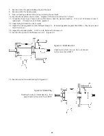
Use the feeler gauge and take a measurement of the gap between the impeller and front case. This will
require the removal of the suction and discharge piping.
b.
If out of specifications, adjust the impeller/case tolerance by the bearing cap jackscrews. (Proper gap
values are listed in table 3)
c.
Loosen the bearing cap lock bolts and the jack bolts several turns. These are evenly spaced bolts on the
bearing cap.
d.
Tighten each bearing cap bolt. These are also three evenly bolts spaced on the bearing cap. (Please note
the jackscrews have an additional nut on the bolt). Remember each turn of the bolt is approximately
5/100”. Evenly tighten each bolt until each bolt gives tight resistance. (At this point the entire rotating
assembly has been pushed its entire allowable distance forward. The impeller is fully pushed against the
case and further travel is not possible. Trying to force the bearing cap lock screws may damage the pump)
e.
Evenly tighten each jackscrew, pulling the rotating assembly from the case towards the motor. Continue
tightening jackscrews making periodic measurements until the impeller/case space is the amount stated
in Table 3.
f.
Tighten the bearing case lock nuts and jack bolts until tight. This step will keep the rotating assembly
secured in its proper place. The impeller tolerance is now set.
g.
Reassemble any disconnected suction piping.
4.
Dial Indicator Method. (This method may used when the back pull is still attached to the case and the case may or
may not be attached to the suction and discharge piping.)
a.
Remove the coupling spacer, hub and bushing.
b.
Tighten each bearing cap bolt. These are also three evenly spaced bolts on the bearing cap. (Please note
the jackscrews have an additional nut on the bolt). Remember each turn of the bolt is approximately
5/100”. Evenly tighten each bolt until each bolt they give tight resistance. (At this point the entire
rotating assembly has been pushed its entire allowable distance forward. The impeller is fully pushed
against the case and further travel is not possible. Trying to force the bearing cap lock screws may damage
the pump )
c.
Place the dial indicator base securely on the base or some other surface not attached to the rotating
assembly and set the rotating dial to zero.
d.
Evenly tighten each jackscrew, pulling the rotating assembly from the case and towards the motor.
Continue tightening jackscrews making periodic dial indicator measurements until the impeller/case space
measurement is as stated in Table 3.
e.
Tighten the bearing case lock nuts taking care not to over tighten and moving the rotating assembly.
The impeller tolerance is now set.
f.
Reassemble the coupling
5. Laser Alignment Method. (This method should be performed in accordance with equipment instructions.)
6-2.5 Motor and Coupling assembly
1.
Reattach the coupling and guard
2.
For alignment refer to section 3-3.
3.
Refer to start up instructions in section 4.


