D
Installing a frost protection device for the drain trap
KLIMA-KOMPONENTEN-KÜCH GMBH
Adolfstraße 16, 57555 Niederschelderhütte-Siegen
Tel.: (02 71) 31 92 66 - 00, Fax: (02 71) 31 92 66 - 01
Internet: www.klima-kuech.com,
E-Mail: [email protected]
KLIMA-KOMPONENTEN-KÜCH GMBH
Adolfstraße 16, 57555 Niederschelderhütte-Siegen
Tel.: (02 71) 31 92 66 - 00, Fax: (02 71) 31 92 66 - 01
Internet: www.klima-kuech.com,
E-Mail: [email protected]
Part 1 and Part 2 A3 as well as
VDE 0254, have to be observed
for the installation of the an-
tifreeze heating. The antifreeze
heating must only be installed
by an authorised specialist. The
electrical connection must only
be carried out by an electrician
in accordance with the electrical
regulations.
Modifications to the heating cable are not allowed.
Damages at the heating cable can cause the ingress
of humidity and dirt as well as arcing and a fire in the
entire system. A heating cable damaged by fire can
cause further fire damage when being switched on.
Therefore such a heating cable must be taken out of
operation immediately.
Intended use
Antifreeze heating for siphons for VAC plants. Assem-
bly and connection must be carried out according to
these instructions. Any use other than that which is
intended shall not be allowed.
Instructions for the
electrical connection
The heating cable of the antifreeze heating must
never be shortened, not even on the PTC thermistor
side. Excess cable lenghts of the heating cable are to
be led through the outlet in the condensate trough
(necessary for example for shortened siphons). The
heating cable is not to be fastened, but just inserted
into the siphon and fixed with the screwing in such a
way that the connecting sleeve is completely outside
the siphon. The heating cable must not be brought
into contact with sharp edges and be protected from
mechanical damage.
the heating cable must not be crossed or touched
anywhere. The heating cable is to be laid in such a way
that no heat accumulation will be caused. The heating
cable must not be led above or through combustible
materials. The electrical protection and the protective
measures must have been provided on the installa-
tion side for which the use of a 30 mA residual-cur-
rent-operated circuit breaker (r.c.c.b.) is mandatory.
The exclusive use of miniature circuit breakers may
not be enough to prevent the progression of arcs and
can provide a fire hazard.
The heating cable of the antifreeze heating must be
operated exclusively from the provided connection
box with the built-in antifreeze thermostat to ensure
that an operation is impossible at ambient tempera-
tures > +5°C. An insulation test is required before the
heating is taken into operation. Pipes used for cable
laying must be included in the protective measures
(grounding of pipes).
The circuit diagram is available as a free download on
our homepage.
Repair
A damaged heating cable must never be repaired but
be replaced by a new one.
Instructions for connection
and installation
The connection box should be easily accessible but
protected from mechanical damage. It should always
be installed in such a way that the cable glands do
not point upwards and the lid can be removed. The
heating cable of the antifreeze heating must be laid
between the connection box and the entry into the
siphon in such a way that any mechanical damage will
be prevented. No dragging is allowed at the heating
cable gland and at the siphon intake..
I N S T A L L A T I O N I N S T R U C T I O N S
Antifreeze heating for Siphons (FSH)
Item No.: 24 (suction side, FSH-S)
Item No.: 25 (pressure side, FSH-D)
The antifreeze heating has been especially developed
for the use in all common suction and pressure side
type siphons with 1½" connection for AH units.
Description
In general the antifreeze heating consits of a flexible
self-regulating and automatic power-limiting heating
cable which is led through the siphon and energized
automatically by a variably adjustable thermostat as
soon as the set temperature is fallen below. Heating
the cable prevents the siphon from freezing.
<
For universal use in all 1½" siphons
<
Easy retrofit
<
Preassembled
Maintenance
The heating cable and the connection box must be
checked in regular intervals for mechanical damages,
and the electrical protection and function of the ther-
mostat for their proper functioning.
The siphon should be checked for contamination
at least twice a year and, if the air is heavily polluted
(e.g. exhaust air from the kitchen), more frequently. It
should be cleaned, if necessary.
Installation
Before installing the antifreeze heating (FSH) in sucti-
on-side siphons just remove the 1½" end cap marked
" A " first; in pressure-side siphons the 90° elbow must
be replaced by the supplied 1½" T-piece.
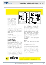
Then push the flexible heating cable into the direction
of the arrow into the siphon (Fig. 2)
It can be necessary in the process to separate the
siphon at the screwings marked " B " because the
somewhat stiff point of the heating cable sticks there
easily, and so it can be pulled through easily from the
other side.
After the antifreeze heating has been screwed using
the preassembled union nut the tightness of all
screwed connections of the siphon must be checked.
Before pressure-side siphons can be taken into opera-
tion again after having been assembled they must be
refilled with water!
They can be refilled through the newly inserted
T-piece which must be closed afterwards using the
previously removed end cap " A ".
For suction-side siphons particular attention has to be
paid that the ball of the non-return valve is not pushed
up by the heating cable because otherwise the functi-
on of the siphon cannot be guaranteed.
Technical data
<
Including connection box (IP 67) with integrated
antifreeze thermostat for installation in the immedi-
ate environment of the siphon
<
Completely equipped with clamps for an easy
connection to the existing electrical supply (3x
1,5mm²), 230 V UPS, max. 10 A
<
Electrical protection by use of a 30 mA residual-cur-
rent-operated circuit-breaker (r.c.c.b.) provided by
the customer
<
Self-regulating and power-limiting heating cable
(70 cm, heated up to the connecting sleeve)
<
Power: 19 W/m (at +10°C) and 30W/m (at -25°C)
<
Protection class I, model with protective conductor
<
Completely watertight in the heated area, from
connecting sleeve
<
Supply cable IP 54 (100 cm, unheated)
<
Admissible operating temperature -30°C to +55°C
<
Thermostat preset to +15°C
<
Hysteresis (switching difference): 6K ± 4K
Example:
required minimum temperature 5°C
Set point 15°C
Resulting from:
required minimum temperature 5°C +
maximum hysteresis 10K (6K + 41K)
Safety instructions
All safety and accident prevention regulations as well
as the guidelines and standards of the country where
the installation is carried out must be observed for
installation and commissioning. Apart from that the
VDE regulations, in particular VDE 0100 and VDE 0721,
Fig. 1
Fig. 2
Installing a frost protection device for th...
Air handling unit X-CUBE X2 / X-CUBE X2 compact
82


