


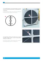


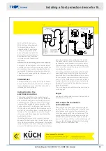


INSTALLATION
Holding belt with tabs to the outside push
end tab through two links (three links for
wedge profiles). Twist tab 90° into place.
9
With your thumb twist second tab 90°.
Push belt end down over tab with your
opposite hand. For wedge profiles,
repeat with remaining tab.
Ensure all tabs are fully turned and
across the belt.
Rotate assembled belt so tabs are inside
(facing down into the pulley groove).
Note:
If take-up system is not available, links can be added to reduce the
tension. If links are added the belt may have to be re-tensioned by
removing the extra links between ½ hour and 24 hours running at
full load.
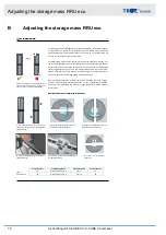
Belt Direction
Force Required to Deflect Belt 1/64" per 1" (16 mm per 1m) Center Distance
Belt
Section
Installation
During Operation
lbs.
Kgf
lbs.
Kgf
3L/O/Z
4 – 4.5
1.8 – 2
3
1.3
A/4L/13
4 – 5
1.8 – 2.3
3
1.3
B/5L/17
7 – 8
3.3 – 3.7
6
2.8
C/22
13 – 15
6 – 6.9
10
4.6
3V/SPZ
5 – 6
2.3 – 2.8
4
1.8
SPA
6 – 7
2.8 – 3.3
5
2.3
5V/SPB
13 – 15
6 – 6.9
8
3.7
FORCE DEFLECTION GUIDELINES
Note:
If deflection force drops below specified force for Operation, remove links
or adjust take-up until belt is back to Installation force.
12
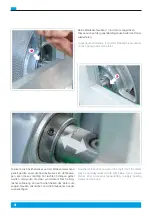
Determine direction of drive rotation. Belt
must travel in the same direction as the
direction arrow. Tabs will trail.
13 A: DRIVE
13 B: WEDGE
Fit the belt in the closest groove of
the smaller pulley. Roll belt onto larger
pulley by turning the drive slowly. The
belt should feel tight. DO NOT JOG THE
MOTOR. Once installed check to make
sure the all tabs are in position and
the belt is not twisted. For multiple belt
drives, work belt from groove to groove.
If the installation with the recommended
# of links removed is too difficult see 13B
Use the belt take up system to install to
the proper tension: position the motor
approximately in the middle of its range
of travel (mark position), hand fit the belt
removing the recommend # of links.
Move motor forward reducing the center
distance enabling easy installation of the
belt(s). Return motor back to original
marked position.
INSTALL ON DRIVE
LEGAL COMPLIANCE NOTICE: For more information regarding the products manufactured, distributed and sold by Fenner Drives and the compliance of such products with applicable domestic and international law, statutes, rules and regulations relating to
human health and the environment (collectively, “Environmental Laws”), including, without limitation Proposition 65 as enacted by the State of California and the Registration, Evaluation, Authorization and Restriction of Chemical Substances (REACH)
as enacted by the European Parliament, please visit www.fennerdrives.com. If you are unable to access our website or if you have any further questions about the compliance of our products with Environmental Laws, you are encouraged to contact the
Fenner Drives’ Environmental, Health, and Safety Manager at +1 (717) 665–2421.
© 2017 Fenner Drives LB–189 02/2017
www.fennerdrives.com
US and Canada • 1 800 243 3374
Latin America • 1 717 665 2421
Europe, Asia, Australia and Africa • +44 0 870 757 7007
11
8
– SIDE 2 –
10
Using a force deflection gauge, check
Installation force and confirm it meets the
requirements below.
14
Pull tight around
pulleys.
1.
Remove extra
links.
2.
Count and remove
designated # of
extra links.
3.
Make endless.
Turn tabs inside.
4.
Roll on to drive
(belt may seem tight).
5.
INST
ALL GUIDELINES
MAKE BELT ENDLESS
ENGLISH
Rotor belt installation instructions
Air handling unit X-CUBE X2 / X-CUBE X2 compact
81


