


Speedy 360
BA 8032_2.2_EN (05/2016)
36 / 90
www.troteclaser.com
13
15
14
5
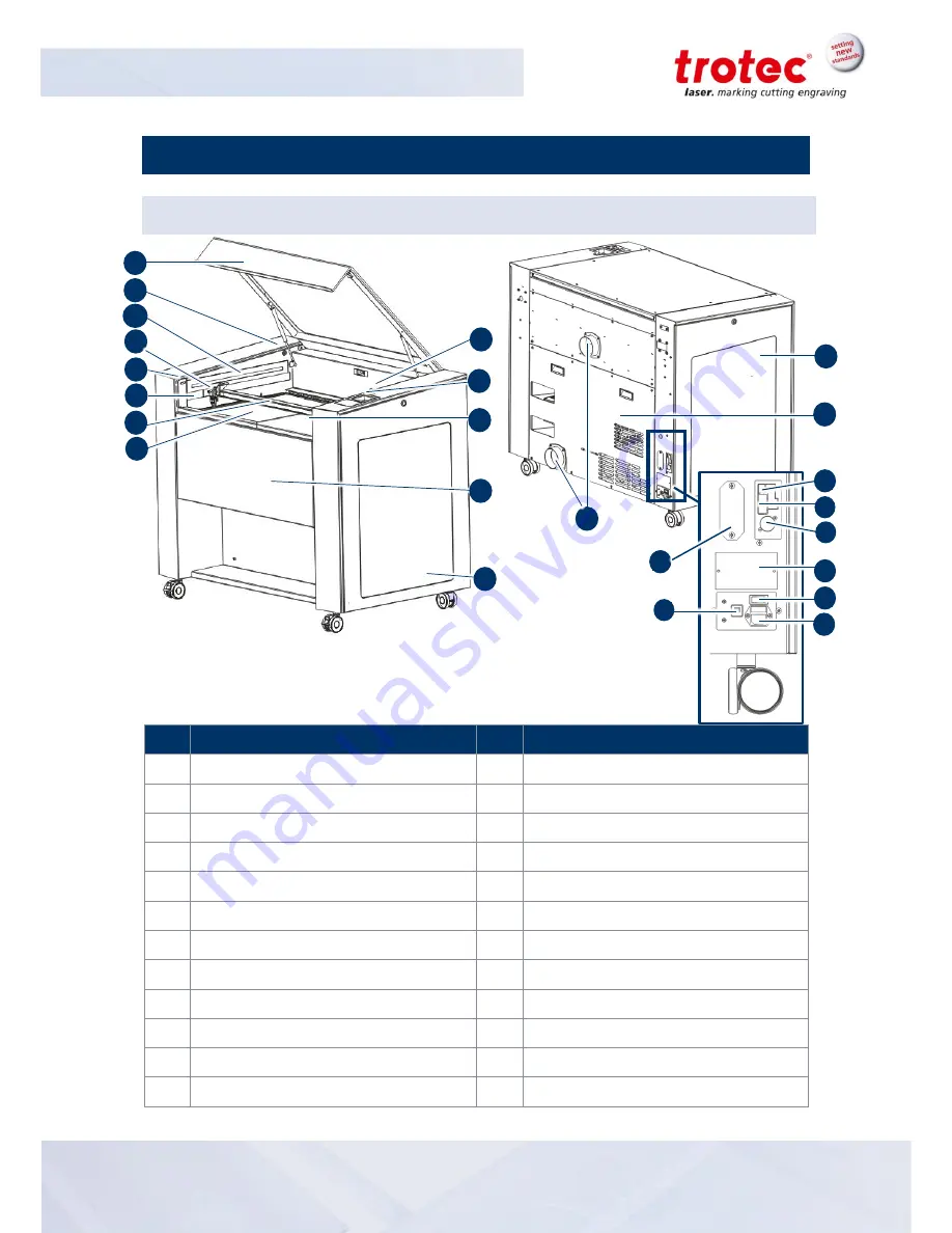
Machine overview
5.1
General overview
No
Description
No
Description
1
Acrylic top lid
13
Side panel left
2
Service plug connector
14
Cover for laser tube and power supplies
3
Laser head
15
Connector for exhaust tube
4
Interlock safety switch
16
USB port for PC
5
Connector for rotary attachment
17
RS 232 port for PC
6
X axis
18
Connectors for exhaust cable
7
Table
19
Type plate
8
Key switch
20
ON/OFF switch
9
Keypad
21
Mains connection
10
Interlock safety switch
22
Connector for JobControl
®
Vision
11
Front door
23
Fuse(s)
12
Side panel right
24
LED interior illumnation
12
1
5
3
8
11
2
4
4
6
7
10
17
16
18
19
20
21
22
23
9
24


