Operation
SeaKing & SeaPrince Imaging Sonars
0374-SOM-00001, Issue: 08
28
© Tritech International Ltd.
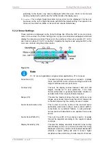
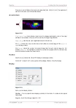
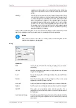
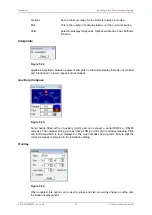
Rng Cross, Rings On, Rings, Grid On - Display Grid line options.
Sector On, Sector – Display a Sector overlay with left and right angular limit adjustment (in
degrees).
Rotation – Rotational offset to correct Sonar heading – (Disabled for Gemini Sonar).
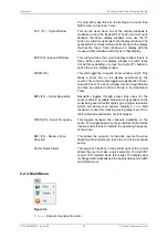
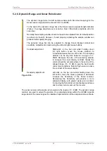
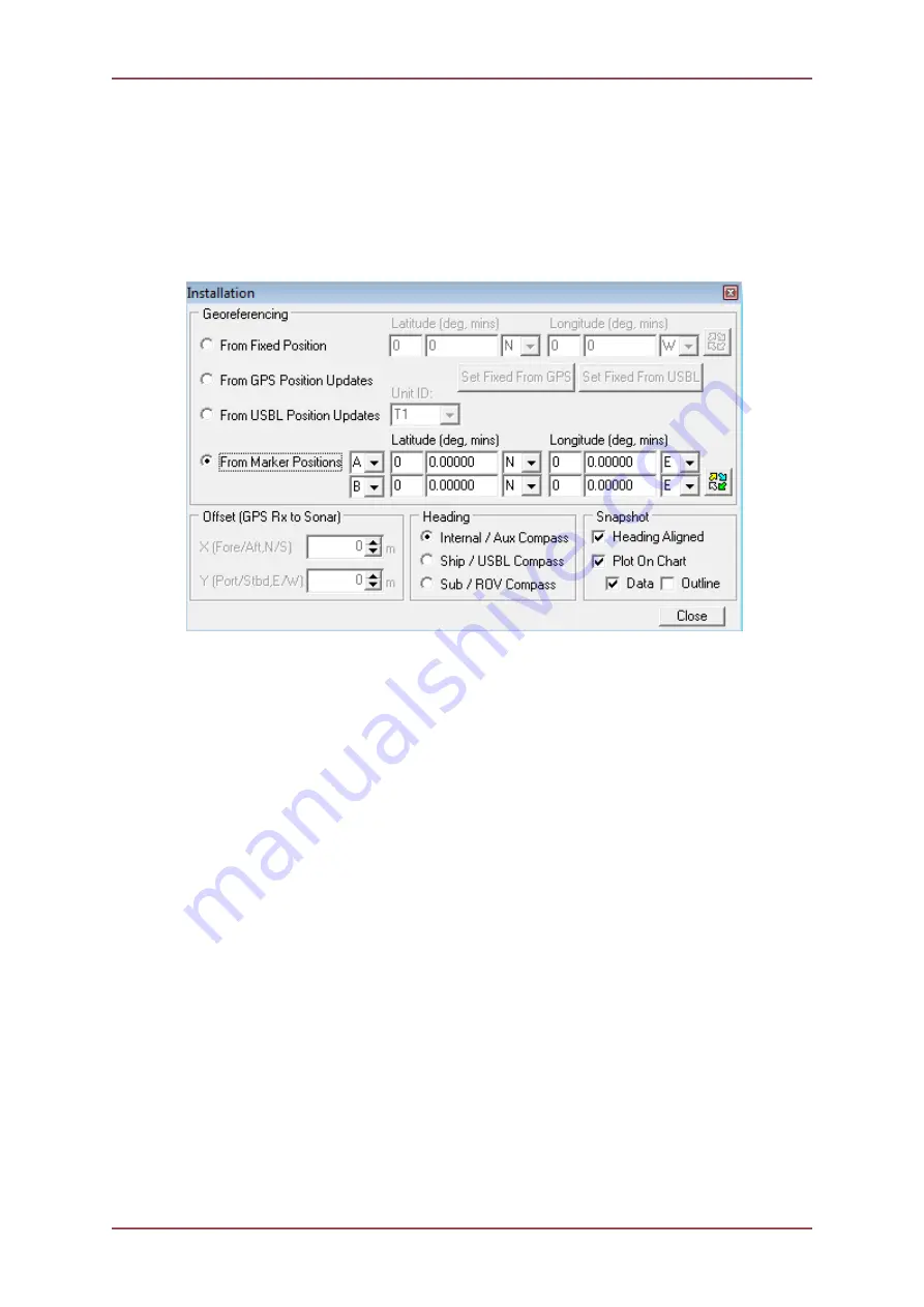
Installation
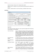
Figure 5.20.
This configures the location of the Sonar in the real world and enables the Geo-referencing
of sonar targets on the sonar display.
From Fixed Position
If there is no GPS input, select this option and input the Sonar
position in Latitude and Longitude co-ordinates (DegMin or
DegMinSec format). A Heading input will also be applied, else a
zero degree heading is applied. If present it is also possible to
set the fixed position from the USBL or GPS input so that they
can be disconnected and the position will remain persistent –
simply click the appropriate button “Set Fixed from GPS” or “Set
Fixed From USBL”
From GPS Position
Updates
If a GPS input is active, select this option. A Heading input will
also need to be active for the Geo-referencing to be functional.
From USBL Position
Updates
If a USBL input is active, select this option. A Heading input will
also need to be active for the Geo-referencing to be functional.
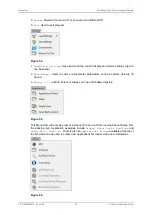
From Marker Positions
This function requires an application with
Sonar
and
Nav
displays
loaded
(e.g.,
by
selecting
Settings
→
Applications
→
Sonar Nav
). The chart of the
Nav
display is used to obtain the Marker position references to
be used in this function. If a
Nav
chart is not used then the Marker
positions must be manually entered in the
Sonar
display.
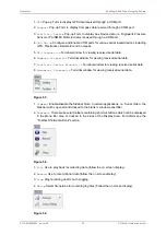
Offset (GPS RX to
Sonar)
X and Y position offsets should be entered if there is any offset
between GPS receiver and Sonar (e.g. for a ship hull mounted
system). Or, for an ROV mounted sonar, if the GPS position

