Maintenance
Intelligent Gyro Compass (iGC)
0707-SOM-00004-7
34
© Tritech International Ltd.
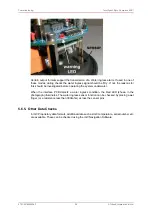
4. Raise the stack of PCBs together and remove the cable end plug (Item 11) from the orange
connector on the Interface PCB.
8.7.3. Removal Of the Underwater Connector
The procedure for removal of the underwater Subconn connector is as follows:
1. Remove the Sensor Assembly, Interface PCB and Processor Module
2. Using a 2.5mm flat-blade screwdriver, remove the connector wires from the plug (Item 11)
3. Using a box spanner or a deep socket (19mm A/F), slacken the connector. Holding the
iGC end-cap (Item 2) in a vice by means of two M5 screws in the mounting holes is the
easiest way to react the torque required to slacken the connector
4. Remove the cable tie from the connector tails. Carefully unscrew the connector and at
the same time, turn the connector wire tails inside the wire gallery. When fully slackened,
carefully feed the wires through the gallery and pull the connector clear. It may be
necessary to remove the bootlace ferrules, or alternatively pull the wires through in stages.
8.7.4. Replacement Of the Underwater Connector
The procedure for replacing the underwater Subconn connector is as follows:
1. If a new connector is to be used, attach heat-shrinkable wire numbers (1-8) to the wire
tails and cut tails to the same length as the removed connector
2. Fit a 30mm length of 4.8mm diameter heatshrink over the connector wire tails. This is used
to protect the wire tails from abrasion when the connector is screwed into the endcap
3. Remove, clean, re-grease and re-fit the connector sealing ‘O’-ring. Ensure that the ‘O’-
ring groove is clean
4. Insert the wires into the connector hole and carefully screw the connector into the endcap
while turning the wires to avoid twisting them
5. When fully home, re-torque the connector with a 19mm A/F box-spanner or deep socket
6. If previously removed or a new connector is being installed, strip wires and fit new bootlace
ferrules to the connector tails. Crimp in place
7. Insert the wires into the 8-way orange connector (Item 11) and tighten with a 2.5mm
flatblade screwdriver. Wires are connected in sequence from pin 1 to 8 of the PCB
connector attached to pins 1-8 of the Subconn. Pin 1 of the PCB connector is identified by
the square pad on the topside of the PCB (it is at the end closest to the regulators).
8.7.5. Replacement Of Sensor Assembly, I/F PCB and Processor Module
The procedure for replacement of the Sensor Assembly, Interface PCB and Processor
Module (as a single unit) is as follows:
1. Insert the PCB stack between the pillars and secure with the 3 x M3 cap screws to the
pillars. Engage the 8-way orange connector when lowering the PCBs into position
2. Slide the insulating washer (Item 18) between the mounting block on the end-cap and the
two regulators. Position this washer so that the holes align with the regulator holes and
tapped holes in the end-cap

