Commissioning
Intelligent Gyro Compass (iGC)
0707-SOM-00004-7
23
© Tritech International Ltd.
5.6.1. Heading Checks
Heading data should be checked against a known good heading reference (e.g. surveyed
Magnetic North reference line or a calibrated gyrocompass). If comparing the iGC heading
against a True North seeking gyro (NSG), the appropriate corrections should be made to the
NSG heading to convert it to a Magnetic North reference prior to checking the iGC.
When the North reference is confirmed, rotate the Host platform that the iGC is mounted to
through 360° heading and check the correlation with the reference gyrocompass or against
cardinal compass points.
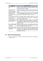
If the data from the iGC is not satisfactory, following steps in Chapter 6,
, may
make improvements.
It should be noted that attempting to check magnetic heading performance on a Steel hulled /
decked vessels or in close proximity to steel structures (e.g. bulwarks, handling system
components etc.) may produce results that are not ideal.
5.6.2. Pitch & Roll Checks
The output of Pitch and Roll should be checked either with the Host system on a known
horizontal flat surface or alternatively against a calibrated vertical reference unit. The iGC
gives accurate Pitch and Roll data over the range ±50° and beyond. Pitch angles that
approach 90° however cause instability with the heading output of the device. This is not
a limitation with the iGC sensors, but with the mathematical angle conversions used in
generating the output data. If users require pitch angles to be measured beyond ±60°, please
contact Tritech for an alternative firmware implementation that does not suffer from this
problem.
Note that only certain Industry Standard telegram formats include the Pitch and Roll data, so
if this data is not requested it cannot be checked.
5.6.3. Heave Acceleration Data Checks
In certain modes, the iGC transmits the raw heave acceleration from its ‘z-axis’ accelerometer
sensor. This can be used for heave compensation systems or for other navigation / survey
purposes.
If the selected operating mode supports this output, check that with the system at rest the
output is nominally 1.00g acceleration or -9.81 ms
-2
depending on the selected telegram
format. By moving the iGC up and down, a change to the heave acceleration should be seen.
Note that certain telegram formats show the acceleration due to gravity, and others remove
this offset prior to transmission.
Note that this output is referenced to the vertical iGC axis, not to ‘earth’ frame. It follows
that the output at pitch and roll angles other than 0° will give a heave acceleration figure
approximately equal to the measured Heave multiplied by the combined cosine of the pitch
and roll angles.
5.6.4. Water Ingress Alarm Checks
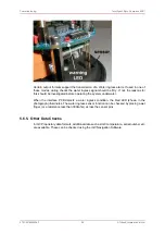
Inside the iGC there is a water ingress detector, comprising two gold pins that extend from
the interface PCB down to the lowest point inside the iGC housing. See photograph below
for details:

