Tripp Lite B020-U08-19-IP Owner'S Manual Download Page 9

2

3

4

5

6

7

9

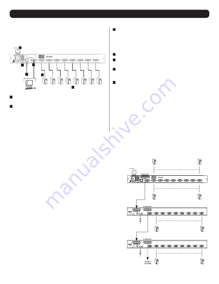
5.5 Single-Station Installation

5.6 Multiple Station (Daisy-Chained) Installation

 5. Installation 

(continued)

To set up your console KVM switch, refer to the following steps and 

installation diagram.

Note:

 The B020-U08-19-IP model is shown in the below diagram. 

The B020-U16-19-IP model differs only in the number of KVM ports.

1


Power OFF all computers that are being connected to the KVM 
switch.

2

 (Optional)

 Add an external console to the KVM by connecting 

the included USB/PS2 console cable kit to the console port on 
the back of the unit, and then connecting an external monitor 

(HD15), keyboard (USB or PS/2) and mouse (USB or PS/2) to 
the connectors on the cable kit. An additional USB port is located 
on the front keyboard panel of the unit as a more convenient 
alternative to the external mouse port on the back of the unit.

3


Connect a P778-Series USB/PS2 Combo KVM Cable Kit between 
an available KVM port on the back of the unit and a computer/

server. P778-Series Cable Kits allow you to connect to a computer 
with either USB or PS/2* keyboard/mouse ports, without the need 

for separate cables. 

Note:

 The distance between the KVM and the 

connected computer must not exceed 33 ft. (10 m).

4


Repeat step 3 for each additional computer you wish to connect.

5


Connect the LAN port on the back of the unit to the network using 
Cat5e/6 cable.

6


Connect the included power cord to the C14 jack on the back of 
the unit, and then plug it into a Tripp Lite Surge Protector, PDU or 
Uninterruptible Power Supply (UPS).

7


First power ON the KVM switch, and then power on the connected 
computers.

*When connecting to computers using the PS/2 connectors of a P778-Series Cable Kit, 

the 

Mouse Sync Mode

 setting must be set to Manual in order to access the computer 

over IP. If 

Mouse Sync Mode

 is set to 

Automatic

,  you will not have mouse functionality 

when accessing that computer over IP. This setting is set to 

Manual 

by default. (See page 

50 for details on changing this setting via the 

Web Management Interface

, or page 40 

to change it via the 

Remote OSD

.)

8

08

8

08

B020-U08

B020-U08

B020-U08-19-IP /

B020-U16-19-IP

To control even more computers, up to 31 B020-U08 KVM Switches can be daisy-chained down from the first station.

Note:

 As many as 264 computers can be controlled from the unit’s integrated console in a complete installation. 

To set up a daisy-chained installation:

1. Ensure that power to all the connected devices has been turned off.
2. Connect the included USB/PS2 Combo Console Cable Kit to the console 

connector on the back of the unit, then connect a monitor, mouse and keyboard 

to the appropriate connectors on the cable kit. The distance between the external 
console and the KVM switch must not exceed 66 ft. (20 m).

3. Use a daisy-chain cable (described in the 

Cables 

section) to connect the 

Chain 

Out

 port of the parent unit to the 

Chain In

 port of the child unit. The distance 

between any two KVM switches in a daisy-chain must not exceed 49 ft. (15 

m). The distance between the first KVM switch and the last KVM switch in a 
daisy-chain must not exceed 328 ft. (100 m), regardless of the number of KVM 
switches in the entire chain.

4. Use a KVM cable kit (described in the 

Cables

 section) to connect the keyboard, 

video and mouse ports of a computer to any available port on the KVM switch. 
The distance between the KVM switch and each connected computer must not 
exceed 33 ft. (10 m).

5. Repeat the above steps for any additional KVM switches and computers you wish 

to add to the chain.

6. To power up the installation:

a. Plug in the power adapter for the first station. Wait a few seconds to allow the 

unit to determine its Station ID.

b. Plug in the power adapters for each subsequent station in the installation (i.e. 

second station, third station, etc.). Each KVM switch has an LED display on its 
front panel to indicate its Station ID (the Station ID for the first station is 

01

the ID for the second station is 

02

, the ID for the third station is 

03

, etc.).

In each case, wait for the Station ID to be displayed on the Station ID LED before 
plugging in the next station.

Summary of Contents for B020-U08-19-IP

Page 1: ...1 W 35th Street Chicago IL 60609 USA www tripplite com support Copyright 2018 Tripp Lite All rights reserved PROTECT YOUR INVESTMENT Register your product for quicker service and ultimate peace of min...

Page 2: ...cal Console OSD F6 Broadcast Mode BRC 14 6 4 7 Local Console OSD F7 Auto Scan Function 14 6 4 8 Local Console OSD F8 Logout Function 14 6 4 9 Local Console Pushbuttons 14 6 4 10 Local Console Hotkey C...

Page 3: ...e buyer and not the manufacturer its distributor or its dealer assumes the entire cost of all necessary servicing repair and any incidental or consequential damages resulting from any defect in the so...

Page 4: ...gins from a browser Support 256 bit AES 56 bit DES 168 bit 3DES 128 bit RC4 and 128 bit SSL Supports RADIUS and LDAP S authentication Flash firmware upgradable via network and included firmware upgrad...

Page 5: ...d and powered on The Port ID LED will display the number of the port that currently has the console s focus The Station ID LED will display the number of the station that currently has the console s f...

Page 6: ...h an external VGA monitor and USB or PS 2 keyboard mouse 4 LAN Port The cable that connects the KVM switch to a LAN WAN or Internet plugs in here 5 KVM Ports The custom wired KVM cable kits that conne...

Page 7: ...rom the power supplies Never push objects of any kind into or through cabinet slots They may touch dangerous voltage points or short out parts resulting in a risk of fire or electrical shock Do not at...

Page 8: ...auto adjustment An auto adjustment automatically configures all the settings for the LCD panel to what the OSD considers their optimum values to be When you have entered the LCD OSD Menu function pre...

Page 9: ...50 for details on changing this setting via the Web Management Interface or page 40 to change it via the Remote OSD 8 08 8 08 B020 U08 B020 U08 B020 U08 19 IP B020 U16 19 IP To control even more compu...

Page 10: ...t interface must be enabled in order to use the IP Installer to assign an IP address See page 42 for details This setting is enabled by default 1 Save the IP Installer exe file from the CD to a desire...

Page 11: ...Set IP address manually Fixed IP check box in the IPv4 or IPv6 settings section depending on your network 6 The IP Address Subnet Mask and Default Gateway fields will be activated upon checking the Se...

Page 12: ...on shut down all computers connected to each KVM switch you are powering off Note It is necessary to unplug any computers that have the Keyboard Power On function If left on the KVM switch will contin...

Page 13: ...V An arrow in this column indicates that the corresponding port is selected for Quick View scanning A sun symbol in this column indicates that a computer is both connected to the corresponding port an...

Page 14: ...el of the built in console Next to each set of pushbuttons is an LED that indicates which Port and Station currently has the focus of the KVM To toggle between the ports on the selected KVM press the...

Page 15: ...1 Invoke Hotkey Mode 2 Key in B After you press B the Beeper toggles On or Off The command line displays Beeper On or Beeper Off for one second then the message disappears and you automatically exit H...

Page 16: ...hes KVM focus to the last port on the station prior to the currently selected port Skip Mode Next station When typed into the hotkey command line this key invokes Skip Mode When in Skip Mode this key...

Page 17: ...ing careful to enter the correct Username and Password In some cases the Administrator may not want the B020 Series KVM Switches to be available via browser The Windows AP Client allows Windows system...

Page 18: ...Switch When you have finished with your session click Disconnect to end the connection Message List Lists status messages regarding the connection to the B020 Series KVM Switch Switch to Remote View...

Page 19: ...ve access will not be displayed in their OSD Double click a port icon to access the device attached to it Once you switch to a port its screen displays on your monitor Depending on whether you have Fu...

Page 20: ...disable defaults You can use the same function keys for more than one hotkey command sequence as long as the first key is not the same For example you can use F1 F2 F3 for one action and F2 F1 F3 for...

Page 21: ...ote screen If the lo cal and remote mouse pointers are not synced performing this function will normally bring them back into alignment If Auto Sync fails to align the screen properly use the Screen P...

Page 22: ...Full Screen Mode is enabled the screen will be stretched to fit the entire local monitor Note Keep Screen Size can only be toggled on off when using one of the Windows clients When using one of the Ja...

Page 23: ...checkmark appears on the icon When set to manual a red x appears on the icon Note This icon is only active on computers that are connected to the KVM using a USB SIU The auto sync functionality only s...

Page 24: ...able Length As the length of Cat5 cable between the KVM and connected computer can affect video quality this setting is designed to compensate for shorter or longer lengths Click to toggle through the...

Page 25: ...ession Lock LEDs These icons display the status of the keyboard Num Lock Caps Lock and Scroll Lock LEDs You can click on them to toggle the corresponding lock function on off When first initiating a r...

Page 26: ...Toolbar are described below Icon Description Click this icon to keep the Panel Array Toolbar visible at all times Click it again to make the toolbar disappear after a few seconds Click and drag any p...

Page 27: ...t Timeout X X X Beeper X X X Edit Port Names X X X Set Port Operating Systems X X Set Port Operating Systems X X Hotkey Command Mode On Off X X Hotkey X X Port ID Display Position X X Touchpad On Off...

Page 28: ...ption ALL Lists all of the ports on the installation that are accessible to the logged on user whether they are powered ON or not POWERED ON Lists all of the ports on the installation that are both ac...

Page 29: ...and Port Name The default is to display both Port Number and Port Name SCAN DURATION This setting determines the amount of time spent on each port when in Auto Scan Mode Key in a value from 1 255 seco...

Page 30: ...ult values except for the network settings port names and user name passwords When this function is accessed a prompt will appear asking if you wish to restore the default settings If yes type in a Y...

Page 31: ...d ON 4 Open the local console OSD and navigate to the F4 ADM page 5 Scroll down to the FIRMWARE UPGRADE option and press the Enter key Press Y to invoke Firmware Upgrade Mode 6 From the computer you d...

Page 32: ...you will find in them Web Browser Main Page When logging into the KVM switch via web browser the following page is displayed The following chart describes the components of this page No Component Desc...

Page 33: ...unctions associated with each of the icons are explained in the following table Icon Description Port Access This page is used to access and control the devices on the KVM switch installation This pag...

Page 34: ...l not be able to access the connected computers 1 When using the Windows ActiveX Viewer and clicking on a port for the first time a screen will open up and you will be prompted to install the Windows...

Page 35: ...ed to the port After a second or two the display changes to provide a text input box 2 Key in a name for the port or change delete a previous one The maximum number of characters allowed for a port na...

Page 36: ...a port is assigned a name it is displayed here Device Name The name of the KVM switch that the port is on Status Current status of the computer or KVM connected to the port Online or Offline Connect...

Page 37: ...view on the left hand panel Note Right clicking on a port that is already in a Favorites book mark will give you the option to cut the port out of that bookmark and paste it into another Favorites bo...

Page 38: ...f time set with this function the user is automatically logged out A login is needed before the B020 Series KVM Switch can be accessed again The default is 30 minutes Toolbar The Toolbar option allows...

Page 39: ...sired setting Full Access This setting is represented by an icon that shows a pair of glasses and a pencil It allows the corresponding account to both view video and perform operations on the selected...

Page 40: ...d provides editable settings related to the connected computer and system macros The contents of this page are described in the table below Setting Description Status Port Status The status of the sel...

Page 41: ...an add edit all account types Adding User Accounts There is a default Super Administrator account on the KVM switch that can be used to set up the KVM switch The default Super Administrator username i...

Page 42: ...on for details Note The Port Configuration setting simply allows for an account to be given Configuration access to the connected ports Configuration permission for each port must still be given via t...

Page 43: ...See Port Configuration section under OSD Operation for details Note For Configuration access to take effect the account must also have been given Port Configuration permission See the Adding User Acc...

Page 44: ...nloaded from www tripplite com support as they become available You can reference this number to see if the version on the website is newer than that on your KVM IP Address The IPv4 address of the net...

Page 45: ...ked the settings fields below will be activated for you to edit IP Address Enter in the desired IP address here Subnet Mask Enter in the desired Subnet Mask here Default Gateway Enter in the desired D...

Page 46: ...will allow to be used to access the log server The valid port range is between 1 and 65535 The default port number is 9001 Note The port number entered here must not be the same as any of the ports e...

Page 47: ...ile is added as an optional attribute to the person class Authentication refers to determining the authenticity of the person logging in Authorization refers to assigning permission to use the device...

Page 48: ...he example below and click OK to complete step 1 of the procedure Common Name userprofile LDAP Display Name userprofile Syntax Unicode String Minimum 1 Maximum 255 Note The Unique X500 Object ID uses...

Page 49: ...g Replace the value shown with su xxxx where xxxx represents the username assigned to the user in the KVM switch User access rights will be the same as those that were assigned to them in the KVM swit...

Page 50: ...of all entries in the database will end with dc tripplite dc com Define the name of the administrator entry for the server rootdn along with its password rootpw This is the server s super user The ro...

Page 51: ...RFC 2849 The figure below illustrates an LDIF file that creates the DIT for the B020 Series KVM Switch directory tree shown in the figure in the previous section The following figure illustrates an LD...

Page 52: ...ount When this checkbox is checked the account used to unsuccessfully access the KVM will be locked out after exceeding the maximum number of failed login attempts Login Failures The Login Failures se...

Page 53: ...with the following having the most impact RC4 impacts performance the least out of the four encryption methods DES is second to least in impact followed by 3DES and AES Of all the possible combination...

Page 54: ...but only when using a HTTP URL Private Certificate When logging into the KVM switch over a secure SSL connection a certificate is required to ensure you are logging into a secure site If a certificate...

Page 55: ...jected If you want to remove the certificate e g to replace it with a new one because of a domain name change click the Remove CSR button The Date Time page allows the user to set the date and time pa...

Page 56: ...ate Start Date Time Check the Start Date Time checkbox and click in the field to the right of it to bring up a calendar that allows you to select a desired date and time Click the Apply button to disp...

Page 57: ...mware Note Super Administrators are the only users who are guaranteed access to the Maintenance section of the KVM Administrators and Users can only access this function if they are given permission T...

Page 58: ...wish to proceed Click Yes to proceed Reset on Exit Check this box and click the Apply button to have the KVM switch reset itself and implement all new settings upon logging out Following the reset al...

Page 59: ...KVM switch via the Add function before the Log Server can start recording its events When you open the Add function the following dialog box will appear Descriptions of the fields in this dialog box...

Page 60: ...t you want the search to start from End Date Select the date that you want the search to end The format follows the MM DD YYYY convention e g 11 04 2005 End Time Select the time that you want the sear...

Page 61: ...this field displays Connected If it is not connected this field displays Waiting A connection status of Waiting means that the Log Server is not communicating with the KVM and will not record its even...

Page 62: ...P C13 to 5 15P Power Consumption 120V 60 Hz 21W 120V 60 Hz 23W Power I P Rating 100 240V 50 60 Hz 1A 100 240V 50 60 Hz 1A Operating Temperature 32 to 122 F 0 to 50 C 32 to 122 F 0 to 50 C Storage Temp...

Page 63: ...ess and release the first key and then press and release the second key Sun Keyboard The PC compatible 101 104 key keyboard can emulate the functions of the Sun keyboard when the Ctrl key is used in c...

Page 64: ...s claims by third parties or otherwise PRODUCT REGISTRATION Visit www tripplite com warranty today to register your new Tripp Lite product You ll be automatically entered into a drawing for a chance t...

Reviews: