background image

9

Installation and Safety Manual

Trinasmart

1. CONFIGURE THE SYSTEM BEFORE GOING TO THE SITE

Before installing the system on-site, you must configure the system online.

1.1    Configure the System Before Going to the Site

If this is your first time configuring a Trinasmart system, create a new user account by going to the Trinasmart website and 
selecting “login”.  From the next page, click on the link that says,  “New Installer?  Sign Up.”  A new page will appear where 
a new Trinasmart account can be created.  Fill in all the fields, and press “Submit” to confirm.  An e-mail will be sent to the 
e-mail address entered.  Click the link provided in the e-mail to activate the Trinasmart account. The link will return to the 
Trinasmart login page, use the new user name and password to enter the site.

1.2    Configure New Installation

In order to properly configure the system, please have the 12 digit code from the Management Unit, and all of the Mac IDs 
from the Optimizers ready before beginning the configuration process. Optimizer codes can be found on the outside of 
the box; this is not recommended if box has been opened. All identification codes are located under the barcode of the 
unit and can be entered manually or with a barcode scanner.

From the “My Installations” page, scroll to the bottom and press the “New Installation” button to create a new site.  You will 
then enter the Configu ration Wizard.  

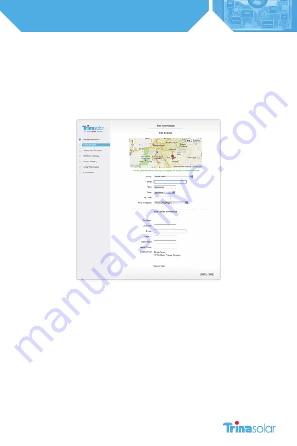
The configuration wizard is a step-by-step process to enter all of the information necessary to configure the system.  
Successful completion of the process will create a system, which will show up on the “My Installations” page.  

1.3    Verify System Information

Once the configuration process is completed, enter the new site and select the ‘Admin’ tab to verify that all of the 
information is correct on the ‘Setting’ and ‘Site Details’ sub-tabs (Fig. 6). 

Most of the information in these sections will have been auto-populated during the System Configuration process. Please 
verify that all of the information entered is correct, and fill in any missing fields if found.

Summary of Contents for Trinasmart

Page 1: ...Installation and Safety Manual TSM_Trinasmart_Installation and Safety Manual_2012_RevB...

Page 2: ...2 Installation and Safety Manual Trinasmart 3simple steps 1 Configure the System Before Going to the Site 2 Install the Management Unit and Gateway 3 Install the Optimizers and verify system...

Page 3: ...ng the Management Unit and Gateway 15 Verifying the System 17 Troubleshooting 23 Technical Specifications 25 per UL 1741 This symbol is used to indicate WARNING Failure to follow instructions may resu...

Page 4: ...PV module with or without the Trinasmart Optimizer attached Installation must be performed by trained professionals only Trina Solar does not assume liability for loss or damage resulting from imprope...

Page 5: ...nal management and performance monitoring In well designed large scale systems Trinasmart Optimizer systems will return up to 8 incremental power output while in residential or commercial systems with...

Page 6: ...the MMU will display PVSAFE PRESSED and Requesting to indicate the command has been sent to the Optimizers As the Optimizers are responding the MMU display will indicate how many have successfully dis...

Page 7: ...user ID password information if already established Installation schematic drawing Phillips and slotted screwdrivers MC4 type connectors 1 male 1 female per string Permanent marker or label maker Dete...

Page 8: ...8 Installation and Safety Manual Trinasmart IDENTIFYING PARTS OF THE TRINASMART OPTIMIZER SYSTEM Trinasmart Module Optimizer MM ES Gateway Management Unit MMU and Gateway cable...

Page 9: ...the Mac IDs from the Optimizers ready before beginning the configuration process Optimizer codes can be found on the outside of the box this is not recommended if box has been opened All identificati...

Page 10: ...wisted pair outdoor rated wire of at least 18AWG See Tigo Energy s website for a list of tested cable options Access the MMU communications ports by pressing the latch at the bottom edge of the clear...

Page 11: ...ight four pin connector in order to wire the outbound RS 485 cable to the next Gateway Only the final Gateway in the series connection should have a termination resistor When finished replace the cove...

Page 12: ...cuit do not use a separate or dedicated power supply DO NOT INITIATE DISCOVERY AND POWER ON UNTIL ALL OPTIMIZERS HAVE BEEN INSTALLED NOTE To verify if a connection has been made to the network the ins...

Page 13: ...ub Array 1 Sub Array 2 Sub Array 4 Sub Array 3 Gateway Gateway Terminated Gateway Position the Gateway at the center of the module cluster and attach to the upper left hand corner of a PV module frame...

Page 14: ...the modules from the Management Unit console Place this label in a visible location on the front surface of the Fuse Combiner Box typically found adjacent to the array in multi string projects AC Disc...

Page 15: ...modules return to the Management Unit and initiate the Discovery and Power On command which will also power on the Optimizers if they not powered on already Access this from the MMU display by selecti...

Page 16: ...communicate effectively with the Gateway By paying close attention to these warning messages the installer can locate the most ideal place for the Gateway to be able to communicate effectively with al...

Page 17: ...andard PV array Refer to the Troubleshooting section for instructions on verifying the system communication is operating properly Please ensure safety precautions are always observed in order to avoid...

Page 18: ...off 3 Push Data Immediately attempts to make another communication to transfer data to the data center without having to wait the usual 10 minute period between communications Useful for real time deb...

Page 19: ...ion can be wired with Cat 5 Ethernet wire The data feed leads A and B on the MMU and Gateway terminal blocks must be connected to the same twisted pair See the table for instructions on connecting the...

Page 20: ...e Gateway This is useful for troubleshooting problems with the system communications See the table below for the meaning of each light pattern Color pattern Gateway Status No color Not powered from MM...

Page 21: ...ccess the web via HTTPS proxy and server is not cooperating Verify proxy settings on MMU Verify proxy server allows access to https datacenter tigoenergy com Re initiate network test No default GW Mis...

Page 22: ...ressing ENTER 4 The next entry field will read SUBNET MASK AND AGAIN 000 000 000 000 Use the four keys as before to move and change the number values 5 The next entry field will read DEFAULT GATEWAY A...

Page 23: ...d if not installed and used in accordance with the instructions may cause harmful interference to radio communications However there is no guarantee that interference will not occur in a particular in...

Page 24: ...nt of ISC 0 053 C Input data MMJ ES50 Maximum Power 300W Maximum Input DC Voltage VOC 52V VMP Range 16 48V Maximum Continuous Current IMP 9 5A Maximum Input Current ISC 10A VMP Voltage at maximum powe...

Page 25: ...ie Street Sydney NSW 2000 t 61 2 8667 3088 f 61 2 8667 3200 e australia trinasolar com United Arab Emirates Trina Solar Middle East Ltd Office 306 Injazat Building Mohamed Bin Zayed City Abu Dhabi P O...

Reviews: