background image

In addition to the primary air, pre-heated secondary air is 

also supplied over the firebed to ensure complete combustion.

W A R N I N G   N O T E S

Fumes:

When properly installed and operated, this appliance will

not emit fumes into the dwelling.  Occasional fumes from

ash removal and refuelling may occur but persistent fume

emission is potentially dangerous and must not be tolerated.

If, despite the operation of the Safety Switch, fumes are

emitted from the boiler then the following immediate

action should be taken:

a.  Switch off the electrical supply to the boiler.

b.  Open doors and windows to ventilate the room.

c.  Let the fire out or safely dispose of fuel from the 

appliance.

d.  Check the boiler flueways and chimney for blockage

and clean as required.

e.  Do not attempt to re-light the fire until the cause of

the fume emission has been identified and corrected.

If necessary, seek expert advice.

Frozen System

Do not attempt to light the fire if it is suspected that any

part of the water system is frozen.

Ventilation

An extractor fan must not be fitted in the same room as

the appliance.

Operating Problems

If in difficulty with the operation of the boiler, refer to the

Fault Finding Chart which indicates most of the common

operating faults and suggests remedies to overcome

them.  If this chart does not provide the answer, contact

your local Heating Engineer for assistance.

Maintaining the Boiler

Routine cleaning maintenance of this boiler is a simple

procedure and can be carried out by the user, but it is 

recommended that a complete service be undertaken

annually by a qualified Service Engineer.

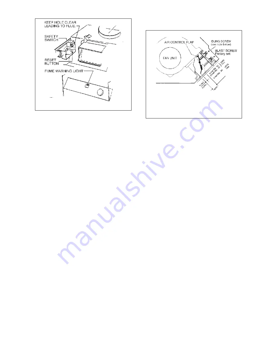
Fig. 2   AIR CONTROL SETTINGS

Fig. 1   

BLOCKED FLUE SAFETY SWITCH

To Light Boiler

1. Check that the boiler is full of water and all valves are open.

2.  Switch on electrical supply to boiler

3.  Ensure that the fuel- regulator is correctly positioned

to suit the fuel being used and fill hopper (see under 
Fuel Regulator Settings)

4.  Thoroughly warm the chimney by lighting two or three

wax firelighters in the boiler flue outlet.

5. After warming the chimney insert three wax fire

lighters in the middle and well up into the firebed.
Light and allow them to burn under natural draught for
3 or 4 minutes. (See Fig. 3 for position of fire lighters)

6.  Close the fire-door., switch on the fan by turning up

the thermostat.

7.  The fire should be well established within approximately

15 minutes, but check to make sure that the fire
lighters have not been extinguished.

8.  The fan will continue to blow  until the thermostat setting

is reached.  Thereafter it will operate automatically,
switching on and off to satisfy the heat demand.

Thermostat Settings

Setting Low 

I

I

I

I

High

Approx Temp. °C  55 

60 

66 

71 

76 

82

The setting selected will depend on the nature of the

load, i.e. whether heating or hot water, the season of the

year and individual requirements.

Typical settings are:

Domestic Hot Water 

55° to 60°C

Early and latter parts 

66° to 71°C

of heating system 

Mid winter conditions

76° to 82°C

Air Control

On a demand for heat, air is supplied to the fire by a 

thermostatically controlled forced draught fan, whereas

during the “fan off” period the fire idles at a low rate of

burning under natural draught.

The air supply for both rates of combustion is controlled by a

balanced flap in the fan throat which is factory set for “blast”

and has adjustment for “idling” if required.(See Fig. 2.)

2

THE IDLING CONTROL SCREW MAY NEED ADJUSTING

TO SUIT INDIVIDUAL DRAUGHT CONDITIONS. IF FIRE

GOES OUT SCREW IN APPROX. 2 TURNS TO PROP

OPEN FLAP WIDER. IF BOILER OVERHEATS SCREW

OUT APPROX. 2 TURNS TO CLOSE FLAP


Summary of Contents for TRG 45

Page 1: ...SOLID FUEL CENTRAL HEATING BOILERS To be retained by householder TRIANCO TRG Range MKII Gravity Feed Forced Draught Boilers EMC 89 336 EEC USER INSTALLATION COMMISSIONING SERVICING INSTRUCTIONS ...

Page 2: ... necessary personal protective clothing or equipment is worn appropriate to parts that could be considered as being hazardous to health and safety The installer should be aware of his responsibilities under the Act and provide where necessary appropriate protection for persons carrying out the installation INSULATION AND SEALS Glass Rope Mineral Wool Insulation Pads Ceramic Fibre Glass Insulation ...

Page 3: ...CONTENTS PAGE 1 USER INSTRUCTIONS 1 2 2 OPERATING DETAILS 3 3 TECHNICAL INFORMATION 4 4 INSTALLATION INSTRUCTIONS 5 6 7 5 SERVICING 8 6 SPARES 9 7 FAULT FINDING 12 13 ...

Page 4: ...l be made for parts and or labour providing An appliance fault is found and the appliance has been installed and commissioned within the past 12 months Reasonable evidence of this must be supplied on request A charge will be made where Our Service Engineer finds no fault with the appliance see note below or The cause of a breakdown is due to other parts of the plumbing heating system including sub...

Page 5: ...lator is located at the back of the hopper to control the depth of firebed Adjustment is provided by means of holes which engage over a hanger peg to suit the fuel being burned The following settings must be used 1 Fuel Regulator Settings Top hole Anthracite Grains 2nd hole from top Anthracite Beans Note Do not allow fuel level in hopper to fall below fuel regulator plate Declinkering Under averag...

Page 6: ...that the boiler is full of water and all valves are open 2 Switch on electrical supply to boiler 3 Ensure that the fuel regulator is correctly positioned to suit the fuel being used and fill hopper see under Fuel Regulator Settings 4 Thoroughly warm the chimney by lighting two or three wax firelighters in the boiler flue outlet 5 After warming the chimney insert three wax fire lighters in the midd...

Page 7: ...2 OPERATING DETAILS 3 TRG 80 TRG 45 60 ...

Page 8: ...in 5 5 5 Maximum Working head 15 8m 52ft Thermostat Adjustable between 55 C and 82 C in six settings Casing White stove enamel with two tone grey facia Insulation Glass fibre lining in side panels Draught Stabiliser Integral part of boiler Based on 160 Btu h sq ft 100 F difference An allowance of 8 000 Btu h has been made for domestic hot water NOTE THE BOILER MUST HAVE A CONTINUOUS ELECTRICAL SUP...

Page 9: ... acceptable temperature at the taps IMPORTANT SAFETY NOTES Read these instructions before installing your boiler IMPORTANT ISOLATE ELECTRICAL SUPPLY TO THE BOILER BEFORE CARRYING OUT ANY WORK The mains supply plug is the primary disconnect device and must be readily accessible during normal use To maintain the boiler s high thermal efficiency and reliable operation it should be serviced annually b...

Page 10: ... there is no means of dissipating the residual heat by way of a hot water cylinder or heat leak radiator then a pump overrun stat must be fitted to the boiler flow pipe Air Supply Adequate ventilation is required to ensure that sufficient air is available for combustion The room in which the boiler is installed must be provided with a permanent fresh air opening of not less than the following 148c...

Page 11: ...ed from a switched plug 5 amp fuse to the mains terminal block under thermostat cover Pass cable along bottom of boiler and through bush in left handside Check operation of forced draught fan by turning on thermostat also ensure that the air control flap pivots freely in fan throat 4 Position the fuel regulator on the appropriate hole to suit the fuel being used see Operating Instructions for sett...

Page 12: ...ce should be carried out as soon as possible after the end of the heating season Boiler Flue Cleaning To maintain the high thermal efficiency of the boiler and to avoid the possibility of DANGEROUS GASES being emitted it is necessary to keep the internal flue ways clear by scraping off deposits at regular intervals weekly in Winter and according to usage in Summer Important Always ensure the speci...

Page 13: ...BOILER BODY ASSEMBLY TRG 80 BOILER BODY ASSEMBLY TRG 45 60 9 6 SPARES ...

Page 14: ...ulator 37056 37272 37590 1 28 Hopper Lid Assembly 36571 36671 37570 1 30 Seal 98178 98178 98178 1 61 Clinker Tray Assembly 36505 36705 37720 1 62 Flue Scraper 38500 38500 38500 1 65 Seal 98178 98178 98178 1 81 Fan Unit 37134 37134 35534 1 86 Thermostat Ranco 206896 206896 206896 1 93 Thermostat Control Cover Assembly 36566 36641 36145 1 98 Blocked Flue Stat 45651 45651 45651 1 10 ...

Page 15: ...92 1 21 TOP ASSEMBLY 37770 1 23 LATCH SPIRE SCO2130 95190 95190 95190 4 FRONT REAR PANEL ASSEMBLY 36581 36681 24 REAR PANEL 36582 36682 25 FRONT PANEL 36586 36686 36686 26 L H HINGE BRACKET ASSEMBLY 36584 36584 27 R H HINGE BRACKET ASSEMBLY 36585 36584 11 LATCH FASTEX ITW 95163 95163 95163 1 16 STUD SPIRE No 5 BV2141 17 95191 95191 95191 4 17 WASHER SHAKEPROOF 4BA92211 92211 92211 92211 4 18 SCREW...

Page 16: ...k seal and replace if necessary Fire door not sealing Check seal and replace if necessary FIRE OUT Insufficient Idling Air Screw in Idling Screw one or two turns to increase air supply Firebed choked with clinker and ash Declinker firebed until fresh fuel is seen and re light Insufficient draught Clean boiler flue ways and sweep chimney Ensure that draught stabiliser closes when draught is low Wet...

Page 17: ...s possible after clinkering Incorrect declinkering Ensure fire is recovered by turning on fan for a few minutes both before and after declinkering Over declinkering Do not declinker more than two strokes at any declinkering operation Hopper allowed to empty below fuel regulator plate and then re filled Always keep hopper topped up and never let fuel fall below fuel regulator plate EXCESSIVE No sys...

Page 18: ...opyright in this brochure and the drawings or illustrations contained in it is vested in Trianco Limited and neither the brochure or any part thereof may be reproduced without prior written consent Trianco Limited s policy is one of continuous research and development This may necessitate alterations to this specification By appointment to H M Queen Elizabeth The Queen Mother Manufacturers of Dome...

Reviews: