background image

2021 E-Caliber Service Manual

15

Carriage wiper seals and bushings (continued)

Remove the carriage seals

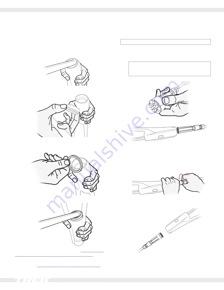
1.  Use the Delrin rod to pull out the front seal.

Tip: 

You may need to move the rod around the car-

riage to remove the seal.

2.  Pull out the foam ring. This is the only foam ring in the 

carriage. 

3.  Use the Delrin rod to pull out the rear seal.

If you are replacing only the seals, jump t

Carriage wiper 

seals and bushings (continued) section on page 17

.

If you are replacing both the seals and the bushings, con-

tinue with the 

Replace the bushings section on page 15

.

Replace the bushings

NOTICE: 

Do not apply grease to the bushings.

1. 

Put the slide hammer with the collet attached inside 

the front end of the carriage.

NOTICE: 

Take care to engage only the bushing, 

and NOT the interior of the carriage. Engaging the 

carriage could damage the carriage.

2. 

Thread the collet to engage the bushing lip

.

Tip: 

Be careful not to engage the lip inside the car-

riage. Engage the bushing only.

3.  Use the slide hammer to remove the bushing.

4.  Repeat steps 1 to 3 to remove the rear bushing.
5. 

Wipe the bushing bores with a clean, dry cloth to 

remove any debris.

Summary of Contents for 2021 E-CALIBER

Page 1: ...2021 E CALIBER SERVICE MANUAL SUPPLEMENT...

Page 2: ...to the specified torque Over tightening hardware could deform or break the hardware or components Under tightening hardware could cause hardware or components to become loose Either situation could da...

Page 3: ...of the upper bearing cover 1 Interlocking keys of the upper bearing cover 1 and the stem 2 Replace any damaged or worn components 3 Apply grease to Upper and lower head tube bearing bores Inside of t...

Page 4: ...2 Down tube guard 1 W582884 3 Drive unit guard fasteners 4 5269023 3 4 Drive unit guard 1 W1040440 Chainstay and down tube guards Use isopropyl alcohol to clean the frame surface where the guards att...

Page 5: ...ou must have the main pivot bearing and sleeve See the Main pivot section on page 6 and the IsoStrut See the IsoStrut section on page 10 installed on the rear triangle before attaching the rear triang...

Page 6: ...rear triangle 4 4 5 8 Install the four bridge bolts 4 to attach the bridge to the rear triangle 9 If applicable install the main pivot hardware before torquing the bridge bolts 4 See the Main pivot se...

Page 7: ...osition the chainstay over the seat tube ensuring that the main pivot holes are aligned Tip Slide the long arm of the hex tool from the non drive side and through the aligned pivot holes For each step...

Page 8: ...thread NOTICE The washer is frame specific Install only the washer compatible with your frame WARNING Do not apply grease to the derailleur hanger or bolt Only apply grease to the thru axle 1 Insert...

Page 9: ...cable guide 2 W519232 8 Head tube cable guide fastener 2 W532763 1 9 Controller cable 1 10 Down tube cable guide 3 W591416 11 Rear derailleur cable 1 12 Grommet for use with wireless derailleur only 1...

Page 10: ...e IsoStrut and out the drive side of the head tube hole 3 At the head tube route the wire through the cable 4 At the IsoStrut slide the ferrule on the wire 5 Guide the wire through the slot in the cab...

Page 11: ...87197 7 Compression sleeve 1 591626 8 Shock oil plug 1 W580727 9 End cap bolt 1 591626 10 Rear IsoStrut axle 1 10 Tools Torque wrench with 5 mm hex bit 1 Assemble the body bolt 5 body sleeve 4 one o r...

Page 12: ...installed on the bike Note the current air pressure 1 Use a shock pump to check the air pressure in the shock Make a note of the current air pressure so you can re inflate the shock after changing th...

Page 13: ...ing is unthreaded from the shock the front end of the shock will extend forwards to reveal an o ring a round metal plate and the air spacer 1 2 3 Item Description 1 O ring 2 Round metal plate 3 Air sp...

Page 14: ...cap as shown below Size small frame the air fill valve aligns with the mounting tab Size medium large and extra large frames the cable hanger aligns with the mounting tab 5 Place the torque wrench in...

Page 15: ...1 inch 25 4 mm Headset press Fork bath oil 10 wt Tools for replacing the bushings Slide hammer 30 36 Expanding collet IsoStrut seal and bushing press tool set Available as part number 593490 Bushing...

Page 16: ...ing both the seals and the bushings con tinue with the Replace the bushings section on page 15 Replace the bushings NOTICE Do not apply grease to the bushings 1 Put the slide hammer with the collet at...

Page 17: ...e rear end of the carriage and lock it into place 10 Spin the headset press until it is snug against the bushing tool Check for the correct alignment of the press tools and bushings Rotate the press t...

Page 18: ...e carriage 4 Insert the upper half of the headset press into the front of the carriage 5 Insert the lower half of the headset press into the rear end of the carriage and lock it into place 6 Spin the...

Page 19: ...the carriage Install the damper body hardware See IsoStrut section on page 10 Add oil to the carriage 1 Use a syringe to fill the IsoStrut with 15 cc of 10 wt oil 2 Firmly press the oil plug back into...

Page 20: ...2021 E Caliber Service Manual 19 Fazua system Service manual and parts Bicycle retailers Refer to the 2021 Domane LT Fazua system manual Consumers Contact your local Trek retailer for assistance...

Page 21: ...ct mount Maximum 230 mm Knock Block steering radius 62 degrees Seat post Minimum insertion WARNING Always follow the seat post manufacturer s minimum insertion recommendation Failure to follow the rec...

Page 22: ...pen sion calculator For recommended rebound settings refer to the suspension calculator at trekbikes com suspension calculator IsoStrut Recommended sag 20 25 1 2 4 3 Item Description Dimension 1 Shock...

Reviews: