background image

www.transvu.co.uk

Configuration & Operation Guide

11

Addendum

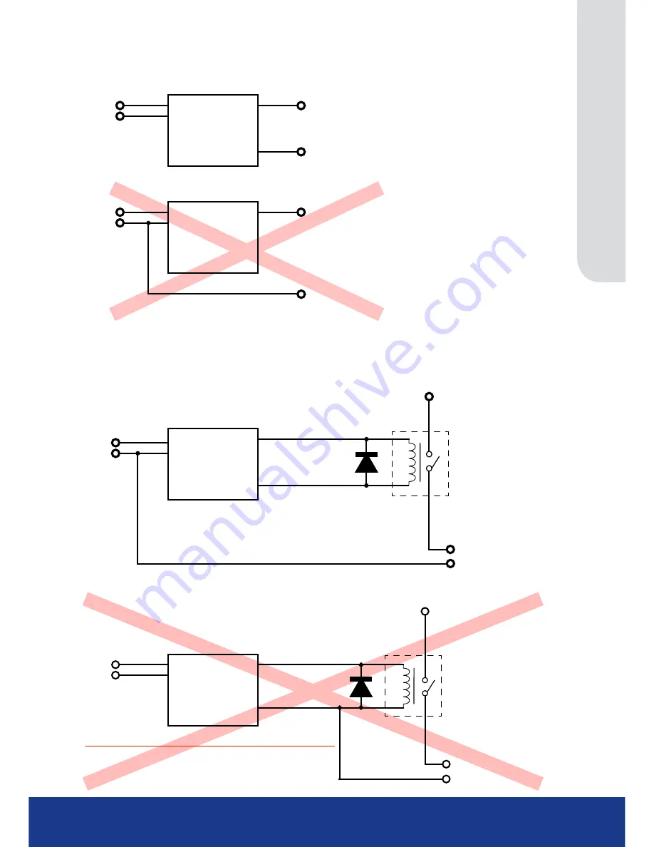
AUX CURRENT UP TO A MAXIMUM OF 1A SWITCHING CASE

Aux GND

+ve To cameras & low power equipment (MAX 1Amp)

GROUND POWERED DEVICE THROUGH DVR

TransVU Compact

Aux Power Out

Aux GND

DC Input +
DC Ground

DC Input +

DC Ground

Aux GND

+ve To cameras & low power equipment

DO NOT GROUND POWERED DEVICE THROUGH PSU

TransVU Compact

DC Input +

DC Ground

DC Input +
DC Ground

Aux Power Out

AUX CURRENT GREATHER THAN 1A SWITCHING CASE

High Cve

+ve To cameras, illuminators etc

GND output

RELAY

TransVU Compact

DC Input +

DC Ground

DC Input +
DC Ground

Aux Power Out

Aux GND

High Cve

Aux GND

+ve To cameras, illuminators etc

RELAY

TransVU Compact

DC Input +

DC Ground

DC Input +
DC Ground

Aux Power Out

Aux GND

DO NOT GROUND HIGH POWERED DEVICES THROUGH DVR

Summary of Contents for Compact

Page 1: ...www transvu co uk Configuration Operation Guide TransVu Compact ...

Page 2: ... 39 Viewer Defaults 40 Display 42 Map Config 43 Map Data 45 User Accounts 46 Camera Settings 48 Setup 49 Overview 54 IP Stream Inputs 55 Record Settings 56 Default 57 Profile Record 58 JPEG Pre Trigger 62 Protect Video 63 AoE Setup 64 Schedule 65 Setup 66 RVRC 68 Holiday Weekend 69 Alarm Settings 70 Inputs 71 Zone Input 73 Zone Actions 75 Masked Cam Det 77 Data Logging 79 Accelerometer 80 Alarm Re...

Page 3: ...es or other high risk areas where health and safety issues place constraints on power supplies Part of the NetVu Connected product range the TransVu Compact is fully network capable and supports the Internet standard TCP IP protocol As the TransVu Compact is a mobile product the unit can be accessed via wireless LAN or GSM GPRS CDPD UTMS HSDPA Supporting up to four video inputs two audio channels ...

Page 4: ...in to ensure maximum compatibility with future developments in networked security NetVu Connected technology enables the Unit to fully interact with other NetVu Connected compatible products from Dedicated Micros including the DV IP Decoder NetVu ObserVer and PDA Viewers Providing interoperability between the worlds leading security companies NetVu Connected uses industry standard networking proto...

Page 5: ...he camera will instantly respond positioning the selected area in the middle of the screen ideal for tracking movement through a scene MAP Users can now navigate around their CCTV installation using a graphical map Selecting the relevant camera from the map will instantly connect the user to that cameras image stream With the ability to load bespoke map images and floor plans to reflect their inst...

Page 6: ...s where lightning is a common occurrence Regulatory Notes and FCC and DOC Information USA and Canadian Models Only Warning This equipment has been tested and found to comply with the limits for a Class A digital device pursuant to part 15 of the FCC rules These limits are designed to provide reasonable protection against harmful interference when the equipment is operated in a commercial environme...

Page 7: ...uide 7 CE Mark If this product is marked with the CE symbol it indicates compliance with all applicable directives Directive 89 336 EEC A Declaration of Conformity is held at Dedicated Micros Ltd 1200 Daresbury Park Daresbury Cheshire WA4 4HS UK ...

Page 8: ... clamped to the same mounting surface as the TransVu Compact This will help avoid any vibration being transmitted along them to the unit Recommended fitment area 285mm 11 x 195mm 7 Minimum height of enclosure 90mm 3 Notes on installation space Additional space is required around the electrical connectors to allow the disconnection of the cables from the unit The unit does not require alignment wit...

Page 9: ...ut 500mA 12V 48V Max NET1 RJ45 Ethernet network connector 10 100 Mb s Ethernet Network NET0 RJ45 Ethernet network connector 10 100 Mb s Ethernet Network Rear Panel Description Function CAM 1 4 75Ω BNC composite video inputs 1V pk pk MON A 75Ω BNC composite monitor output 1V pk pk STEREO AUD IN 3 5mm phono socket 8KHz 16KHz 22KHz sampling 75Ω input impedance 1V pk pk STEREO AUD OUT 3 5mm phono sock...

Page 10: ...OM2 RS485 1 2 3 4 5 6 7 8 9 ALARMS RELAY 1 RELAY 1 A 2 RELAY 1 B 3 TACHO IN 4 Digital GND 5 Ignition 6 ALM1 wake on alarm 7 ALM2 8 ALM3 9 Digital GND PWR IN 1 DC Input IGN 2 Ignition 12V OUT 3 DC Ground 4 Alarm 5 Aux Ground 6 Aux Power Out GPS Pin Conn Description 1 N A No connection 2 DGND Digital ground 3 AT_RXD ATMega88 GPS receive data RS232 4 AT_TXD ATMega88 GPS transmit data RS232 5 5V 5V GP...

Page 11: ...ow power equipment DO NOT GROUND POWERED DEVICE THROUGH PSU TransVU Compact DC Input DC Ground DC Input DC Ground Aux Power Out AUX CURRENT GREATHER THAN 1A SWITCHING CASE High Current ve ve To cameras illuminators etc GND output RELAY TransVU Compact DC Input DC Ground DC Input DC Ground Aux Power Out Aux GND High Current ve Aux GND ve To cameras illuminators etc RELAY TransVU Compact DC Input DC...

Page 12: ...ask and default gateway will automatically be allocated from the network DHCP Server DHCP is enabled by default Note If a DNS Domain Name Server address is not to be used it is strongly advised that a fixed IP address be assigned a DHCP assigned address can change without notification i e following power failure A fixed IP address can be assigned via the Configuration Menu Network Settings Network...

Page 13: ... 13 Accessing the Configuration Webpages The unit can be configured using the webpages To access these 1 Launch Internet Explorer or similar web browser package 2 Type the URL for the unit IP or DNS address 3 The Opening menu page will be displayed ...

Page 14: ... in the Features menu System Settings Features Select the Viewer menu tab to access the unit s Viewer function Refer to Unit Operation for information on the numerous Viewer features Select the Download menu tab to access the various Download sub options Select from Product Manual Select to open an electronic version of the Installation Operation Guide ObserVer Manual Select to open an electronic ...

Page 15: ...sernames and Passwords are required to access any of the various menus Usernames and Passwords can however be added to regulate access to the Configuration and Viewer menus Refer to the Display Settings User Accounts menu for information on establishing Usernames and Passwords ...

Page 16: ...e Relevant menus can also be accessed directly from other menu screens via the coloured softkey options shown at the base of each menu The options available will depend on the menu being viewed Select a softkey option by pressing either the corresponding button on the IR Remote Control if viewing the menus locally or by selecting the relevant option via the PC mouse if viewing the webpages Note An...

Page 17: ...The Serial Ports page allows each of the two serial ports to be individually configured for one of a range of operations including debug PPP and telemetry The Power Manager page allows the configuration of power saving procedures such as the timeout limits for ignition off and low voltage level detected The Audio page shows the settings available for each of the audio channels and allows configura...

Page 18: ... be edited to allocate a name to the unit This is displayed when the unit is accessed via NetVu ObserVer and is sent when transmitting information to a Remote Video Response Centres RVRC Video Standard Displays the video standard adopted by the unit i e PAL NTSC Number of Cameras Shows the number of camera channels on the unit Video Storage Gbytes Highlights the available video storage capacity in...

Page 19: ...ng Loader Revision This identifies the bootloader version the unit is running Webpage Revision This identifies the webpage version the unit is running PC Apps Revision This identifies the revision archive of the Viewer and associated PC Apps software Boot Software Rev Displays the infrastructure componentry software revision Applet version This identifies the version of the Java applet installed o...

Page 20: ...eason The reason for the last restart is displayed i e Controlled User Reset Current PPS Displays the current system record rate Codecs Details the current number of installed codecs Cameras Lists the available camera connections Connected Camera channels with cameras connected will be highlighted light green Those not in use will appear dark green Recording Camera channels that are recording will...

Page 21: ...nd the relays Outputs Alarm Contacts Details the state of the alarm contacts Contacts will display dark green when open passive light green when closed active Alarm Zones This details the status of the 6 available alarm zones Zones will display dark green when passive light green when active Relay Outputs The relay output will display dark green when open light green when closed ...

Page 22: ...figured correctly on the unit but the unit has never received any data from the connected GPS device Data Timeout This means the GPS was sending data but has timed out and not sent anything for about five seconds or more GPS Disabled In theory this should never be shown as the GPS status page cannot be accessed with the GPS disabled but if the page is already on screen and someone disables the GPS...

Page 23: ...ils the Overall satellite data Last Read PGRMT Details the Sensor status information Any GPS device that outputs the GPRMC string will work with TransVu Compact About This menu allows access to numerous system information pages Select the an icon to view the relevant pages refer to Appendix E Status Pages for a description of each page System Information Select to open to the System Attributes pag...

Page 24: ...The log files stored in the unit can be accessed from this page Selected logs are displayed on the page below About Blue Select to open the System Status About page Refresh Purple Refreshes the information on the current page ...

Page 25: ...ed the language can also be changed for the current session only System Language Select to change the system language setting Reset Red Select to reset the unit Note The unit MUST be reset to implement system language changes Session Language Select to change the language settings for the current session only Choose Select to immediately activate session language changes ...

Page 26: ... also be displayed as mm dd yy or yy mm dd Time Format As default the time displayed is in 12 hour format This can be changed to 24 hour if required SNTP Server A Simple Network Time Protocol SNTP server allows external devices to connect and set their current date and time settings to that of the SNTP If required enter the SNTP server IP address here Set Time Enter a current time for the unit Set...

Page 27: ...ts the port for connection to a TransVu LED Status Box Interface Type Choose the type of serial interface being used Select from COM1 RS232 COM2 RS485 RS422 Baud These options allow the Serial port communication settings to be configured Parity These options allow the Serial port communication settings to be configured Data These options allow the Serial port communication settings to be configure...

Page 28: ...ng switched Off to the unit powering down Low Supply Timeout Enter a time in seconds from a low voltage supply being detected to the unit powering down Minimum Supply Enter the minimum voltage level at which the unit will commence a forced shutdown Nominal Supply Enter the nominal voltage at which the Low Supply Timeout function will activate Ignition Enabled Select Enabled to activate the ignitio...

Page 29: ...after startup Enter the time in seconds after which the application will stop attempting to synchronise to the GPS device GPS String Logging The option allows selection of which strings from the GPS are logged The options are GPRMC GPGGA GPGSA and PGRMT These strings detail the status of the GPS unit including position status and date and are saved to file Wake unit on GPS Enable or Disable the fe...

Page 30: ...activate Record Gain This option allows the Record Gain level to be set This is the base setting from which the AGC Automatic Gain Control will operate Select from 1 to 15 The default and recommended setting is 15 Playback Volume Select a volume setting between 1 to 64 for audio playback Record AGC Select this option to activate the Automatic Gain Control AGC function AGC amplifies audio until a r...

Page 31: ...tioning System function refer to System Settings Status GPS Status for information regarding the GPS unit Remote Reporting Select this option to activate the Remote Reporting function refer to Network Settings Remote Reporting for more information Note When de selected here the Remote Reporting menu will no longer be displayed in the menu tree Data Logging Select this option to activate the Data L...

Page 32: ...ted here the Camera Masking menu will no longer be displayed in the menu tree SMS Select to use Short Messaging Service SMS Suitable external hardware is required Refer to Appendix B for further guidance SMB server support Select this option to activate the SMB Server Message Block file sharing function When activated the SMB protocol allows the unit to access PCs operating the Windows operating s...

Page 33: ...use the default port settings 1025 Select User Defined to use settings entered in the Telemetry Port option Telemetry Port Enter the port settings for telemetry data here The default setting is 1025 Note This option will only be displayed when User Defined is selected in the Telem UDP Port Selection option Samba Workgroup Enter the Samba SMB Workgroup details Note A unit reset is required to activ...

Page 34: ...and minimise the comb effect that may be visible when recording high motion scenes in 4CIF mode Comb Filter Enable this option to activate the Comb Filter function Comb Filter can help improve the fine details of a video signal image by filtering the luminance and chrominance separation process Disable Transcoding Select to disable the unit s transcoding capabilities In normal circumstances this s...

Page 35: ...ised applet Enable Event Search Page Select to enable the Event Search option When enabled the option will appear within the Configuration Menu tree Refer to Navigating the Configuration Menus Event Search for further details Enable RVRC page Select this option to activate the RVRC Remote Set Unset Override function refer to Record Settings RVRC for more information Note When de selected here the ...

Page 36: ...ected media Restore Blue Select to restore previously saved settings from the selected media Note Selecting the Restore button will cause the system to reboot To From Select the relevant media device to save to or restore from i e USB Export Logs Export Logs Yellow Select to export all Logged data to a connected external device To Select the relevant media device to save to export to Server Reset ...

Page 37: ...tickbox es to select deselect installed PowerScripts then select Save Green A system reset will be required for the changes to take affect Note Changes this page will alter the Default C file If you already have a custom PowerScript on your unit which uses Default C please contact AD Technical Support for guidance Tel 44 0 845 600 9502 for further guidance ...

Page 38: ...ies held in it Function Description Last database reset time This read only section is generated by the unit and identifies the last time that the database was reset Current number of entries This read only section shows how many events are held in the database Reset database This button will clear the database and set the last reset time to the current time and date ...

Page 39: ...rol whether text will be displayed on the Main or Spot monitors the colour of that text and how long cameras being displayed in sequence will be shown on screen The Map Config page allows images to be imported and used as maps displayed in the Viewer menus Hot spots can be added to allow quick navigation to individual cameras The Map Data page allows Map Config information to be saved for future u...

Page 40: ...be displayed in either High Medium or Low resolution Default Multi Display When accessing the Viewer function select the display format which will initially be displayed Startup Multi Display When accessing the Viewer function select the display format which will initially be displayed Startup Camera When accessing the Viewer function select the camera image which will initially be displayed If on...

Page 41: ...ocation of the unit s Viewer menu applet is displayed The default location will always be the applet installed on the unit If accessing multiple units via a remote connection all can be assigned the same Viewer applet This will lessen the load time required when accessing different DVRs Servers For example if a local unit and a remote DVR are to be accessed it is possible to set the Applet locatio...

Page 42: ...can be set from 1 to 99 seconds The dwell time is the period a camera s images are displayed before switching to the next camera in the sequence Sequence main on startup Select to sequence live views from all connected cameras on the main monitor upon system start up Softkey Timeout Enter the number of seconds unused key inputs on the monitor output will be displayed before disappearing Enable cus...

Page 43: ...hese coordinates represent the top left corner of the map graphic as displayed in the Viewer menu Camera Select Select which camera is to be linked to the created hotspot Activate Hotspot Select to activate and display the camera hotspot Hotspot Radius Enter the radius in pixels of the hotspot Increment by If using the Decrement Red or Increment Green buttons enter the size in pixels that the hots...

Page 44: ...d from its current location The absolute positioning point will depend on the data entered here A setting of 0 would result in the camera facing its Original base position To change the preset position enter a number between 1 and 360 A setting of 20 would set the preset position to 20 degrees to the right of its origin position 180 would send it to face in the opposite direction of its base posit...

Page 45: ...only be available when viewing the menu pages remotely i e via the webpages To save map data highlight and copy all text displayed in the Map Data text window then save this data as a text file To import data copy relevant text from an external location and paste into the Map Data text window When the menu is exited this data will be used as the Map Config settings Note If importing data remember ...

Page 46: ...FTP function will limit access to the Video FTP archiving feature used with DM s NetVu ObserVer Telnet Assigning username and password requirements for Telnet connections will limit Telnet access to the unit Telnet can be used to upgrade the unit Serial Assigning username and password requirements for Serial connections will limit access via a Serial link Menu Configuration Assigning Menu Configur...

Page 47: ... connected to on the rear of the unit For example if wanting to allow access to camera 1 to 3 inclusive enter 1 3 If wanting to grant access to cameras 1 3 and 6 enter 1 3 6 If no camera data is entered access will be allowed to all connected cameras in both live and playback modes Note There are no default usernames and passwords for any of the Account Types If none are assigned access will be gr...

Page 48: ...nected local camera channels The Overview menu details the general settings assigned to each of the local camera channels The IP Stream Inputs page allows third party IP cameras to be integrated into the unit The Camera Setup page allows the colour and contrast settings for each individual camera to be adjusted with a dynamic preview available The Camera Telemetry page enables telemetry capable ca...

Page 49: ...times the same alarm is triggered within an hour period If the detector is triggered the number of times entered here the unit will set the camera to No Connection To disable this feature leave the setting as 0 Title Assign a recognisable name to the camera This will be displayed in all references to the camera in the both the Configuration and Viewer menus Type The settings will default to Colour...

Page 50: ...gning camera presets after X mins Refer to Default to preset Note The following settings will change depending on the type of camera connected If a Local Analog Camera is selected Colour Select a colour value from 8 to 8 via the slidebar or enter a number directly into the accompanying textbox Brightness Select a contrast value from 8 to 8 via the slidebar or enter a number directly into the accom...

Page 51: ...elected the unit will utilise the codec in the remote NetVu connected video server camera to allow change Multimode profiles and perform additional activities such as VMD and Activity Detection as if the codec was an integral part of the DVR If Remote codec is selected the loading on the unit s internal codecs will be reduced IMPORTANT The Remote codec option is only applicable for NetVu Connected...

Page 52: ...ochrome cameras are used select Mono Selecting Mono will remove colour patterning If a particular channel is not in use or the camera has failed select Not Connected Term Cameras that are not being looped through to another piece of equipment will need to be terminated Double termination not removing termination from the unit will result in the 1V peak to peak video signal being crushed This can r...

Page 53: ...pe Allows selection of fisheye depressive fisheye and normal lens types Pitch Allows the image to be rotated counterclockwise by ninety degrees Ratio H Allows the horizontal ratio of a panamorphic lens to be set Ratio V Allows the vertical ratio of a panamorphic lens to be set Ratio x100 Allows the multiplier ratio of a panamorphic lens to be set Cam Setup Red Select to open the Camera Setup page ...

Page 54: ... to any of these cameras Click on Local Camera Setup to edit the settings held in the unit Click on Setup to open the Setup menu on the connected video source CIP Settings Red Select to open the Closed IPTV Settings page Unalloc Green Select to open the Camera Unallocated Cams page Refresh Purple Refreshes the information on the current page ...

Page 55: ...as to be added to the TransVu Compact Channel Select a camera channel for review and adjustment Copy to all Select this option to apply current settings to all connected sources Comp Shows the compression type on the IP Stream during the schedule setting Res Displays the resolution of the IP Stream during the schedule setting ...

Page 56: ... appropriately to the alarms and time of day A high degree of control and flexibility is possible using these options The JPEG Trigger page allows configuration of the pre trigger feature for cameras recording JPEG mode only When enabled the pre trigger feature will buffer and store alarm recording prior to an event trigger The Protect Video page allows previously recorded data to be protected and...

Page 57: ...s in alarm Days Recording Displays the record duration possible using the current configuration Timed Expiry If required all stored recorded video can be permanently deleted after a set number of days Set to 0 to de activate this function Camera Settings Choose the rate of non alarm recording to be used from the range of preset recording profiles Select from Normal Rate MPEG4 5pps Normal Rate JPEG...

Page 58: ...le Record Menu View Switch to the Advanced Profile Record menu Channel Enables selection of a specific camera for editing Copy To End Select to copy the current profile record settings to all camera channels Copy To Next Select to copy the current profile record settings to the next camera channel Filter By Allows filtering by resolution only standard resolution is currently available Unset Set Ov...

Page 59: ...es can also be recorded at Real Time speed 3 4 Real Time or 1 2 Real Time To disable record choose the No Record option Select User Defined to use settings established in the Advanced Profile Record menu Quality The accompanying dropdown list allows the quality of recorded images to be set Select from Maximum Very High High Medium or Low Select User Defined to use settings established in the Advan...

Page 60: ...copy the current profile record settings to the next camera channel Filter By Allows filtering by resolution only standard resolution is currently available Unset Set Override Normal Shows the recording profile used by the camera if no Timed Schedules are applied and the camera is operating under Normal non Event conditions Refer to Schedule for further information Unset Set Override EventShows th...

Page 61: ...ithin the range of 45 2500K bits second Size If JPEG is selected the figure entered here will be the size of the JPEG transmitted in Kbytes JPEG file sizes can be configured within the range of 5 45Kbytes PPS Select the number of pictures recorded per second GOP If using MPEG4 recording select the number of images recorded within a GOP Group of Pictures A GOP consists of an I Frame keyframe and fo...

Page 62: ...cording prior to an event trigger in JPEG format It will use the maximum available memory dependent on other cameras requirements of the buffer space Select Enable to activate Note It is recommended that the Pre Alarm option in the Alarm Settings Zone Input menu be set to the same value as the Pre Trigger setting This will ensure successful playback of high quality Pre Trigger images High quality ...

Page 63: ... end date to protect video End Time Enter an end time to protect video Protect Length days Enter the number of days that selected files will be protected for Protect Green Select this option to protect recorded video for the selected time period s Unprotect All Red Select this option to unprotect all recorded video from the list List From Date Time This dialog box allows a search to be made within...

Page 64: ...Viewer Menu Copy Menu for guidance on exporting Event data via the unit s USB port IMPORTANT An additional ini file must be installed to make use of the AOE feature Please contact Dedicated Micros Technical support team 44 0 845 600 9500 for guidance Note Contact Dedicated Micros Technical support team 44 0 845 600 9500 for details of recommended AOE devices Logical Devices Connected AOE Devices A...

Page 65: ...in Set or Unset mode combine with different recording qualities and rates under normal and alarm conditions for a high degree of control in a range of situations The Setup page allows configuration of the schedule including naming the modes of operation and controlling when the unit changes between modes The RVRC page allows the Schedule to be changed to force a Day Night or Weekend condition The ...

Page 66: ...be entered for Unset Set and Override mode Note Any changes to Mode titles here will affect the mode names displayed in the Profile Record IP Record and Zone Input menu pages Current Mode Shows the current timer mode according to the names entered in the Mode Title text boxes Day Time Enter the time using the 24hr clock when Unset mode will begin Night TIme Enter the time using the 24hr clock when...

Page 67: ... the standard name settings for the profiles SET UNSET If these names have been changed on the Schedule page these menu options will display the user configured names UNSET Time Specifies what time in format HH MM the UNSET recording settings configured on the Profile Recording page will become operational SET Time Specifies what time in format HH MM the SET recording settings configured on the Pr...

Page 68: ...ezone the unit is in Current PC Time The current date and time information of the PC currently being used to view the webpages will be displayed This will be logged with any override action PC GMT offset in mins Displays the difference between the PC and GMT Current system state The current system state will be displayed i e Set Unset or Override Note The system state names displayed here will dep...

Page 69: ...eyswitch has been enabled in the Record Settings Schedule menu Keyswitch Disabled Holidays Enter a date and press the Add button The date will be added to the Holiday list To delete highlight and select Delete Weekends Select Enable to activate the Weekend function Set mode will now be active for the dates outlined below Start Select a Start day and time for Weekend mode End Select an End day and ...

Page 70: ...eshold contact value and dwell time The Data Logging page allows configuration of which changes in forces applied to the accelerometer are logged The Accelerometer page allows set up and orientation of the unit s 3 axis accelerometer used for measuring acceleration braking turning forces and vertical shock The Alarm Response page enables configuration of responses following an VMD Activity Detecti...

Page 71: ...t as Normally Closed the default setting the alarm will trigger when the input is opened Note If EOL alarms are to be used this option should not be selected i e leave set as Normally Closed EOL The End Of Line EOL option enables the inputs to detect any changes in the electronic input resistance A change outside the expected values will result in a Tamper Alarm short circuit or open circuit being...

Page 72: ... If it is again triggered more than the amount set in the nuisance counter it will remain de activated for another hour This will continue until the trigger value falls below the nuisance count setting To disable this feature leave the setting as 0 Stuck Time min If any of the alarms detectors are active for a period longer than specified here they will automatically be omitted This time period is...

Page 73: ...ps alarms and initiate actions when an alarm is activated there are 32 configurable zones Title This information is stored along with the relevant images in the database ensure this has relevance to the alarm zone Pre Alarm sec This is the time period prior to the start of the alarm included with the alarm recording for archive These images will also be protected from being overwritten Note It is ...

Page 74: ...being triggered immediately This allows staff entry without triggering an alarm prior to switching the system to Set mode Exit route Zone This creates deferred alarms along a specified route while the exit time is active This is in compliance with BS8418 the British Standard for remote video reporting centres Diverting from the exit route during the countdown will result in the alarm being trigger...

Page 75: ...econdary Cameras This setting gives the facility to assign additional cameras to the zone These cameras will become part of the alarm sequence shown in the Viewer menus when the alarm zone is triggered Create Database Entry An alarm activation will be added to the database The zone title will be used as part of the entry information Alarm Relay Select to trigger an alarm relay following zone activ...

Page 76: ... Preset Camera The preset camera is the camera which will be sent to a designated preset position upon alarm activation Preset Enter the preset position number for the selected camera here refer to Unit Operation PTZ Program for more information on establishing camera preset positions Relay Select an onboard or external relay to automatically close on receipt of an alarm Relay Duration Enter in se...

Page 77: ...e Activation Select Zone Activation Camera Displays the camera number and camera title as configured on the Camera Setup page On Enables or disables the feature on the camera Dwell This is the delay the unit will wait before declaring the camera is masked Threshold Defines the threshold the system uses to define that a camera is masked Contrast Defines the contrast threshold the system uses to def...

Page 78: ...TransVu Compact 78 Zone Activation On Mask Defines the Zone trigger that will be activated when the view is masked On Clear Defines the Zone trigger that will be activated when the view is unmasked ...

Page 79: ...rm Select the alarm input to be logged Channel Select the Data Channel to be logged in Vehicle Logging the options are Panic Brake Accel Turn_Left Turn_Right Beacon or Siren On Enable or disable the feature N O Select if the alarm is normally open or closed DSK Log the alarm data to disk Detection Select the type of Voltage detection to be logged Tacho Select the Tacho Speedo channel Channel This ...

Page 80: ...ich direction the units connection ports are facing Deceleration Enter the g limit for a deceleration event to be logged For example an emergency stop will register approx 0 7g plus Acceleration Enter the g limit for a acceleration event to be logged For example a fast saloon car may register approx 0 5g Left Enter the g limit for a tight left turn event to be logged For example a fast saloon car ...

Page 81: ... uk Configuration Operation Guide 81 Threshold The limit above which the force in question will need to exceed to trigger any one event Event Limit Enter a name to appear in the database when responding to a G event ...

Page 82: ...ion option is selected here will result in the camera channel being only available for editing in the relevant configuration menu i e if Activity is selected for Channel 1 this channel can only be edited for Detection in the Activity Setup menu and not the VMD Configuration menu Activity To Trigger Following Activity activation select Simple Response to trigger specific chosen responses from the o...

Page 83: ...alarm relay following zone activation Select the specific relay via the Relay option Email Image If this option is selected a JPEG will be added to the reporting email if Email Reporting is selected Enable in Unset This will enable Activity Detection when the unit is in Unset operation mode Enable in Set This will enable Activity Detection when the unit is in Set operation mode Enable in Override ...

Page 84: ...elation to a PTZ camera Selecting Active while at Preset 1 will result in Activity mode functioning only when the camera is at preset position 1 Select Active while camera not in motion for Activity mode to function only when the camera is still Select Always Active for Activity mode to be in constant operation Activity Channel This is a drop down list of the video inputs on the unit selecting an ...

Page 85: ...R Remote Control If viewing on a local monitor place a cell by pressing the OK button If viewing via the webpages use the mouse to navigate across the image use the left mouse button to place a cell Reload Img Red This option will update the still image displayed in the Grid Editor Set All Green This option will insert a default square of 16 x 16 cells across the displayed video image Clear All Ye...

Page 86: ...cific requirements VMD can only be accessed and configured remotely via the webpages Camera This is a drop down list of the video inputs on the unit selecting one of the inputs will display the corresponding video source Ensure this corresponds with the selected Channel Zone There are 16 VMD zones within the image that can be individually configured select the zone from the drop down list A select...

Page 87: ...ere there are no changes expected Zone disabled This will disable the zone mode Pixel Count This value is set as a percentage and equates to the percentage of pixels in the selected zone that must change for the VMD event to be triggered The default setting is 20 Pixel Change This setting is a percentage value of the overall change required in the grayscale to be included in the pixel count The pe...

Page 88: ...isplayed on the local monitor Select Jump To Primary Camera from the drop down list to activate this function Revert Display Mode Enable this setting to make the unit return to the view displayed before the alarm activation once the alarm has ended Alarm Display Alert Enable this setting to display an alarm text alert in the colour specified in Alarm Colour in the Zone Actions Menu Normally Select...

Page 89: ...e unit s camera inputs to be forwarded to a port address enabling multiple viewers to view live data using a suitable media player without the need to directly connect to the unit The Email page allows configuration of the Email feature The unit can automatically transmit an e mail to an SMTP Server following an event i e on receipt of an alarm or a camera failure notice The Remote Reporting page ...

Page 90: ...g of 1 2 or 3 is available Ethernet MTU bytes This is the maximum transmit unit for the Ethernet packet The MTU is the largest physical packet size measured in bytes that the network can transmit By default this figure is set to 1500bytes Mx Transmission Timeout ms This is the time in milliseconds the unit will wait to re send a packet if an acknowledgement is not received PPP Base IP Base address...

Page 91: ...es For MPEG4 the figure will be the bit rate allocated A higher rate will provide better quality picture display JPEG file sizes can be configured in the range of 5 45Kbytes and MPEG bit rates in the range of 45 2500Kbits second PPS This shows the number of pictures transmitted per second For JPEG the actual images transmitted will depend on the bandwith of the link increasing the pictures sent pe...

Page 92: ...t Rate to High 32 A higher quality setting may result in a lower transfer speed I Frame Ratio Select the ration of I Frames recorded between each P Frame Note An MPEG I frame is considerably larger than a P frame Therefore the higher the IP ratio the higher the disk space required to store recorded images ...

Page 93: ...olan VLC media player Note Multicast can only used for live viewing requests for stored images and events will still need to be made via the Viewer menu Multicast Address Assign a unique IP address This address is not assigned to any physical unit The VLC program will use this address when configured to do so as its multicast group and access any broadcast images via the configured port address se...

Page 94: ...h users can access the images Enter one of the following numbers 0 restricts video to the same host 1 restricts video to the same subnet 32 restricts video to the same site 64 restricts video to the same region 128 restricts video to the same continent 255 is unrestricted in scope ...

Page 95: ...Username If a username is required to access the mail server enter it here Password If a password is required to access the mail server enter it here Recipient Email This is the e mail address of the intended recipient Display Name Recipient This is the addressee name that will be shown in the email name field Reply to Email This field must be configured if the recipient is to reply to an e mail T...

Page 96: ...tection feature Send Image Select to send accompanying image from supporting primary camera Email Image Res Select resolution settings for images sent as thumbnail attachments Choose from Thumbnail LO low res MED medium res and HI high res Log Email Select to log every e mail transaction that the unit issues ...

Page 97: ...ing IP address you must enter the details in both the primary and secondary connection settings Secondary Dial Profile It is possible to select a separate dial profile for the secondary host Public NAT Address This is the public IP or domain name for a unit connected to the Internet via a NAT Router or Firewall This field should be left blank if NAT is not used e g a private network Video Server P...

Page 98: ...ior to sending reporting data Note Some routers will not respond to Ping Alarm Responder Port This specifies the network port number used for reporting to the alarm server In normal circumstances this should be left at the default value 23 Dial Retry Time secs If the initial connection attempt fails the unit will wait for the specified time period in seconds before attempting to re connect Dial Co...

Page 99: ...loaded to the webcam server it is the directory where all images will be saved on the server Image Filename Prefix This is an identifier for images sent from the unit and will be stored as a prefix to the file name Username If it is necessary to use an authentication process to access the webcam server enter the relevant username here Password If it is necessary to use an authentication process to...

Page 100: ...e default port for FTP use is port 21 If this port has already been allocated on the network it is possible to identify and allocate an alternative port Status Server Port Default The default port for the Server Status function is port 23 if this port has already been allocated on the network it is possible to identify and allocate an alternative port number FTP Root Drive and Directory This is th...

Page 101: ...e for the download to take place each day Poll time Minutes If Polled has been selected in Download Options enter the number of minutes which will elapse between the conclusion of one archive download and the start of the next Clear video protection after download This automatically clears the image protection from successfully downloaded images Watermark each partition This enables a watermark to...

Page 102: ...mmunicate with the unit using a TCP port that is not within the open range even with a valid IP address access will not be granted to the unit The enabled ports can be a range or single port address if a single port is needed then enter the sameport number in the to and from section Open UDP ports This option can identify which system UDP ports are available If a host tries to communicate with the...

Page 103: ...icsCapable Please call AD on 44 0 845 600 9500 for further information on our range of Analytics based solutions The Text In Image page allows the unit to integrate text data with recorded images i e a cash register with a camera positioned at the point of sale The Keyword page can be used in conjunction with the Text in Image function Keywords can be entered which when detected will trigger an al...

Page 104: ... designed to work with the AnalyticsCapable TransVu The range of applications include Automatic Number Plate Recognition ANPR Object Left and Removed Detection Tripwire and Counting Tripwire For further information regarding the range of AD Analytics solutions please call 44 0 845 600 9500 ...

Page 105: ...on from the drop down list Copy To All Select to copy the current text in image settings to all camera channels Text Port Type Select the input source for Text in Image data Select Off to switch the function off select Network to use the unit s Network port or Serial to use one of the unit s serial ports see Port below Port All serial ports on the unit support the option for Text In Image For seri...

Page 106: ...r disables the Keyword feature allowing the unit to treat certain pre programmed words received via the text stream as event triggers refer to Keywords for guidance on creating Keyword triggers Keywords pulse extension This time period allows multiple instances of a word received within a period of time to be treated as a single event i e if a configured Keyword is detected again within the first ...

Page 107: ...ta and treat them as alarm zone inputs In turn this generates events in the event database The advantage of this feature is that it allows the user to see exactly which keyword triggered an alarm A total of 32 Keywords can be configured and each can be up to 20 characters in length All of the keywords will be active on the selected Zone keyword channel refer to Zone Input Input Note Increasing the...

Page 108: ... program to the archive It is recommended that this option be selected as it will ensure the downloaded video images can always be successfully viewed Check Media button Selecting this option will display the space required in megabytes for the chosen event period to be fully downloaded The space currently available on the USB device is also shown Archive Space Required Space required for archive ...

Page 109: ...tered in order to isolate and highlight events that are of interest View Defines whether the debug settings on the debug output will be displayed Filter Specifies which of the Debug Filters is being configured Search text Specifies the text to be searched for in the Debug stream Text colour Allows configuration of the parser window font colour Background colour Allows configuration of the parser w...

Page 110: ...esults page Start Date Enter a Start Date for the Event Search Start Time Enter a Start Time for the Event Search End Date Enter an End Date for the Event Search End Time Enter an End Time for the Event Search Cameras Select the camera channel s to be included in the Event Search A range of cameras can be selected by entering a hyphen between the first and last required camera i e 1 8 A selection ...

Page 111: ...o playback an event That event will then playback in the window at the top of the menu Note To zoom into the event currently in playback mode right click it with the mouse The Set Zoom Level option will be displayed The image can be set to display at up to 800 of its recorded size Note that the view window will not increase in size use the scroll bars to navigate the enlarged image IMPORTANT Still...

Page 112: ...hout this section are those displayed remotely via the webpages If viewing locally the menu layout will differ slightly The function of the keys will change according to whether the unit is in Live or Playback mode Overleaf are described the available Viewer menu pages To display the colour coded menu options when viewing locally press the OK button on the IR Remote Control or click the mouse butt...

Page 113: ...y one if pressed again i e if cam 1 is shown top left cam 2 top right etc then the views will increment to cam 2 top left cam 3 top right etc Note When a camera button is pressed to select a new camera the new selection will be displayed in the top left hand corner of the display The next three connected cameras will be displayed in the following three positions Blue Map Displays either the defaul...

Page 114: ...eo playback functions i e play pause rewind and fast forward Red ll Freezes current video display Green Rewinds current video Yellow Plays from current position Blue Fast forwards video up to current recording position Purple Next Opens the next page of the Viewer menu ...

Page 115: ...ellow Event Displays the Events menu Blue Menu Setup Opens the Configuration menu pages IMPORTANT Selecting this option will exit the Viewer menus This will be logged in the User Activity Log as the current user terminating the session refer to Appendix C for further information regarding the User Activity Log Purple Next Opens the next page of the Viewer menu Menu will be displayed in the local v...

Page 116: ... have been established for the PTZ camera select the Preset option and enter a preset number Refer to the Presets menu page for further details on establishing preset positions Yellow Patrol If Patrols have been established for the camera select the Patrol option and enter a number Refer to the Patrols menu page for further details on establishing Patrols Blue Prog Opens the Dome Menu Option page ...

Page 117: ...local monitor To re send the camera to this position select the camera then press Next Preset preset number Note When entering a new preset any previous preset assigned to that number for the same camera will be overwritten Yellow Select This option will send the camera to the stored Preset1 position Blue Set Origin The Origin option allows a base position to be established for the Oracle dome cam...

Page 118: ...s will be overlaid across the screen Green Select This option enables sub menu content selection dependent on the protocol selected Please refer to the specific camera documentation for further guidance Yellow Return This option enables sub menus to be exited dependent on the protocol selected Please refer to the specific camera documentation for further guidance Blue Menu Exit This option will fu...

Page 119: ...from prior the current playback time Selecting the Hour button Green will progress the video to a point exactly one hour prior to the time shown in the date time display Selecting the Hour button Yellow will progress the video to a point exactly one hour in advance of the ime shown in the date time display Selecting the 4Hrs Blue button will change the softkey options to four hour segments i e the...

Page 120: ...time is shown in the bottom left corner of the playback image Timeline The timeline allows navigation from the time and date currently shown in the Date Time Display window The scale changes to correspond to the time period chosen for investigation i e if a scale of one hour is selected it will be possible to move up to one hour prior or one hour in advance of the displayed time unless that select...

Page 121: ...ne hour selecting this button will increase it to four hours selecting it again will increase it to one day etc Left Navigation Arrow Green Selecting the left navigation arrow will play recorded images from the maximum prior time available via the current timeline i e if a one hour time scale is displayed selecting the Left Navigation Arrow will play video from one hour prior This can also be sele...

Page 122: ...K button to display the full list When viewing remotely selecting any Event with the mouse will display the full Event list If viewing locally press PLAY on the IR Remote Control Keyboard to playback an event If viewing remotely highlight a chosen event with the mouse to playback Red Expand CollapseSelect to expand collpase the Event Listing Green Live Select to view live images from the currently...

Page 123: ... Search menu Red Copy Select to add the currently highlighted event to the Copy menu Green Clear All Select to clear ALL events from the copy menu Note Single events can be deleted via the Copy menu Yellow Filter Select to display the Filter Search menu refer to Operating The Viewer Filter Search for further guidance Blue Activity Select to open the Activity Search menu refer to Operating The View...

Page 124: ...ll data currently displayed in the Filter Search Box Green Reset Select to reset the Filter Search box The current Time Date will be displayed plus all available cameras Yellow Now Select to enter the current Time Date Any additional displayed search criteria will remain Blue Apply Select to apply any changes made to the Filter Search box Purple Close Select to return to the Event Copy and Search ...

Page 125: ...as can be selected by entering a hyphen between the first and last required camera i e 1 4 A selection of individual cameras can be chosen by entering a comma between each camera i e 1 2 4 Events captured by other cameras will be ignored Text If searching for text in image events enter the required text here Type The event search can be filtered to include all or specific event types only The even...

Page 126: ... a camera channel Use the Grid option to select a specific segment of the camera view Red Blank Select to remove all data currently displayed in the Filter Search Box Green Reset Select to reset the Filter Search box The current Time Date will be displayed plus all available cameras Yellow Grid Select to open the Grid menu Blue Apply Select to apply any change made to the Filter Search box Purple ...

Page 127: ...ect an end time for the Activity filter Events after this time will be ignored To Date Select a end date for the Activity filter Events after this date will be ignored Cameras Select which camera to include within the Activity search A range of cameras can be selected by entering a hyphen between the first and last required camera i e 1 4 A selection of individual cameras can be chosen by entering...

Page 128: ...ayed in the Activity Search menu for the chosen camera channel Red All This option will display a default rectangle of 18x16 cells across the video image Green None This option will delete all cells from the displayed video image Yellow Start Highlight a cell using the Directional buttons on the IR Remote Control if viewing remotely and select Start Yellow This will mark the start point of the are...

Page 129: ...An area NOT to be included in the Activity zone will be created linking these points IMPORTANT The area cells highlighted yellow constitutes the activity detection zone Any activity events occurring within the area created using the Start and and End points will be ignored Note Multiple zones can be created within the same camera view Purple Finish Select to return to the Activity Search menu ...

Page 130: ... the estimated size of the download the period the images are protected for and the camera channels to be included in the download To Edit an archive within the Copy menu click on it directly use the left mouse button when viewing remotely The textboxes within the Start Finish Protect Days and Cameras fields can be edited as required Selecting a blank Archive line will allow direct entry of data i...

Page 131: ... of completion Red Copy Select to begin the download process Green Delete Select to delete the highlighted archive only Yellow Clear All Select to delete ALL archives currently displayed in the Copy menu Purple Exit Select to exit the Copy menu Note You can navigate away from the Copy menu and the archive procedure will continue To Copy Events Images to a USB Device 1 Insert a USB Device into the ...

Page 132: ...layed in the lower left segment of the main monitor Green Display Select to remove the on screen text displayed on the main monitor Blue Seg Select to custom configure a quad or multiscreen display First ensure the viewer is displaying in Quad or Multiscreen format then select Seg The camera view in the top left segment will be highlighted When the chosen camera is displayed select OK The next cam...

Page 133: ...d on the unit for as long as any related video files are kept One log file will be created daily as a text file and will be named automatically using the date of creation and stored in the logs directory on the unit This can then be downloaded via ftp if required Action Stored Data User Login Username Local or Remote Login Local Archive Username Local or Remote control Media Remote Raw Archive 1 h...

Page 134: ...nection to a Telnet listener at the destination The command specifies a callback profile to use so this can be used to initiate an Internet connection from the server and report the dynamic IP assigned to that connection back to the destination CALLBACK password destination profile text password SMS password to enable commands to be executed destination IP address or DNS name of the Telnet listene...

Page 135: ...tude Current longitude if known Zone Current zone Shutdown SHUTDOWN name time latitude longitude zone Name The system name Time The local julian time of the message Latitude Current latitude decimal degrees if known Longitude Current longitude if known Zone Current zone Distance GPS This message is generated if the unit has moved more than the distance specified on the SMS configuration This can b...

Page 136: ... This message is generated if the unit is using route tracking and has moved into a valid zone after being reported as off track ONTRACK name time lat long speed course zone distance Name The system name Time The local julian time of the message Lat Current latitude decimal degrees if known Long Current longitude if known Speed Current speed reported by GPS Course Current heading reported by GPS Z...

Page 137: ...e system name Time The local julian time of the message Lat Current latitude decimal degrees if known Long Current longitude if known Speed Current speed reported by GPS Course Current heading reported by GPS Zone Current zone Alarm This report is generated when the current active alarm list changes ALARM name time active alarms Camfail This report is generated when cameras fail or restore CAMFAIL...

Page 138: ... ini Algeria Nigeria Iceland no DST gmt_1 ini Libya Chad Congo no DST gmt_2 ini Jerusalem Isreal Johannesburg S Africa no DST gmt_3 ini Nairobi Kenya no DST gmt_4 ini Dubai UAE no DST gmt_5 ini Dehli India no DST gmt_7 ini Bangkok Thailand no DST gmt_8 ini Hong Kong no DST greece ini Athens Istanbul Minsk moscow ini Moscow St Petersburg Volgograd mst ini US Mountain Standard Time mstaz ini US Moun...

Page 139: ...Video Storage Solid State storage via microSD card USB or AOE Audio Audio Inputs 2 x Mic or Line sensitivity Mic input level 25 to 500 mV Line input level 50 to 1000 mV Frequency response 150 Hz 3500 Hz Mic Line select Software selectable Mic bias channel 2 only 3V 3mA max software switchable Alarms 3 x alarm inputs 1 x ignition sense 7V min activates when power management is enabled On Board Indi...

Page 140: ...TransVu Compact 140 Appendix E Status Pages General Information About Blue Select to open to the System Status About page Refresh Purple Refreshes the information on the current page ...

Page 141: ...Details This menu provides information on the type of camera i e analog or IP and for IP cameras the recording status and the supported profiles About Green Select to open the System Status About page Refresh Purple Refreshes the information on the current page ...

Page 142: ...u provides detailed information on the type of camera i e analog or IP and for IP cameras the supported resolution and capabilities About Green Select to open the System Status About page Refresh Purple Refreshes the information on the current page ...

Page 143: ...ation Guide 143 Capabilities Select to open the Capabilities menu This menu details the function capabilities of the unit About Blue Select to open the System Status About page Refresh Purple Refreshes the information on the current page ...

Page 144: ...led on the unit If multiple units are being accessed remotely all can be assigned the same Viewer applet to lessen the load time required when accessing different DVRs Servers refer to the Viewer Defaults menu for further guidance Display Settings Viewer Defaults About Blue Select to open the System Status About page Refresh Purple Refreshes the information on the current page ...

Page 145: ...the different settings available in the record configurations The current default settings are indicated by crosses Choose Setting Select the profile tables of the host product About Blue Select to open the System Status About page Refresh Purple Refreshes the information on the current page ...

Page 146: ...to each of the local camera channels To edit the settings assigned to any of these cameras Click on Local Camera Setup to edit the settings held in the unit Click on Setup to open the Setup menu on the connected video source Refresh Purple Refreshes the information on the current page ...

Page 147: ...dix D 138 Archive 107 Archive 107 Attributes 17 Audio 29 Basic 51 Callback 133 Camconfig Details 141 Camera Lens Configuration 52 Camera Overview 145 Camera Settings 47 Camfail 136 Capabilities 142 Care in feeding cables 8 CE Mark 7 Change Scale 120 Command Format 133 COMMON CONFIGURATION INTERFACE 4 Configuration 35 Connections 9 Console Settings 38 Contents 2 Copy Menu 129 Database 37 Data Loggi...

Page 148: ...address 11 Logs 23 Main Menu 13 Maintain 35 Make Ethernet Connection 133 MAP 5 Map Config 42 Map Data 44 Masked Cam Det 76 Mono Colour Camera 48 Multicast Setup 92 Navigating The Configuration Menus 15 Network 89 Network green button 32 Network Settings 88 Notes on installation space 8 Offtrack GPS 135 Ontrack GPS 135 Operating the Viewer 111 Other blue button 34 Overview 53 Position GPS 134 Posit...

Page 149: ...ings 16 Technical Specification 138 Text In Image 104 The TransVu Compact range includes 3 Time and Date 25 Timed GPS 135 Timeline Navigation 118 Time Scale Options 119 Time Zones 137 To Copy Events Images to a USB Device 130 TransVu Compact dimensions 8 UI Information 143 Unit Status 19 User Accounts 45 User Activity Logging 132 Ventilation 6 Video Control 113 Video Timeline 119 Video yellow butt...

Page 150: ...MI I TVCO E1 2 Copyright AD Group 15 11 2012 www transvu co uk TransVu AD Holdings PlC 1200 Daresbury Park Daresbury Warrington WA4 4HS United Kingdom Tel 44 0 845 600 9501 www transvu co uk ...

Reviews: