95
RTAA-IOM-3
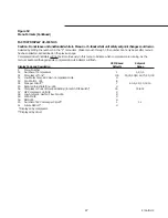
Figure 52
Menu Formats (Continued)
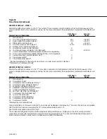
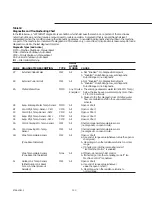
AUXILIARY OPTIONS – MENU 3
Selected by setting the number 3 in the “P” menu number position. Compressor/circuit indicators will not be lit continuously
in this menu to indicate which compressors/circuits are running.
UCM Based
Setpoint
Display Code and Description
Defaults
Range
P
Menu Number
30
External Chilled Water Setpoint - d/E
d
31
External Current Limit Setpoint - d/E
d
32
Ice Machine Control - d/E
d
33
Active-Ice Termination Setpoint*
34
Front Panel Ice Termination Setpoint
27 F
20 to 31 F
35
Return Reset - d/E**
d
36
Zone Reset - d/E**
d
37
Outdoor Reset - d/E**
d
38
Reset Ratio Setpoint***
Return
50%
10 to 120%
Zone
100%
50 to 300%
Outdoor
10%
-80 to 80%
39
Start Reset Setpoint***
Return
10 F
4 to 30 F
Zone
78 F
55 to 85 F
Outdoor
90 F
50 to 130 F
3A
Maximum Reset Setpoint***
Return
5 F
0 to 20 F
Zone
5 F
0 to 20 F
Outdoor
5 F
0 to 20 F
3b
External Circuit Lockout d/E
d
*Dashes are displayed for the setpoint when the chiller is not in the “Ice Building” or “Ice Building Complete” mode.
**The UCM will permit only one type of reset (Return, Zone, or Outdoor) to be selected at one time. For example, if Return
Reset is enabled, an attempt to enable Zone Reset would disable RETURN RESET and enable Zone Reset automatically.
***The UCM contains setpoints for each of the types of reset. The setpoint displayed will be for the type of reset enabled.
If no reset is enabled, dashes will be displayed.
Summary of Contents for RTAA-130
Page 2: ... American Standard Inc 1991 ...
Page 8: ...8 RTAA IOM 3 ...
Page 24: ...24 RTAA IOM 3 ...
Page 50: ...50 RTAA IOM 3 Figure 30 Refrigerant Circuit Identification ...
Page 52: ...52 RTAA IOM 3 Figure 31 Remote Evaporator Piping Example ...
Page 59: ...59 RTAA IOM 3 Continued from Previous Page See Notes on Next Page ...
Page 63: ...63 RTAA IOM 3 Continued from Previous Page See Notes on Page 61 ...
Page 65: ...65 RTAA IOM 3 Continued from Previous Page See Notes on Page 61 ...
Page 76: ...76 RTAA IOM 3 ...
Page 92: ...92 RTAA IOM 3 Figure 51 Operator Interface Controls ...
Page 120: ...120 RTAA IOM 3 ...
Page 127: ...127 RTAA IOM 3 Continued from Previous Page 2307 1566C ...
Page 128: ...128 RTAA IOM 3 Figure 57 Unit Sequence of Operation RTAA 130 to 200 Tons 2306 9122A ...
Page 132: ...132 RTAA IOM 3 Figure 58 Operator s Log ...
Page 138: ...138 RTAA IOM 3 ...

