


45
RTAA-IOM-3
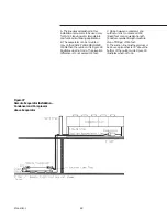
Domestic Water Heater
Piping
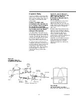
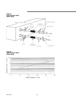
Figure 24 illustrates typical domestic
water heater piping components.
Components and layout will vary
slightly, depending on the location of
connections and the water source. See
unit submittals to insure identification
of water inlet and outlet connections.
Be sure to provide additional vents at
high points in the piping to bleed air
from the water system.
Caution: To prevent damage to
components, do not allow
domestic water heater pressure
(maximum working pressure) to
exceed 150 psig.
Use rubber vibration eliminators to
prevent vibration transmission through
the water lines.
Install a balancing valve in the leaving
water line to control water flow
balance. Install shutoff valves on both
the entering and leaving water lines so
that the domestic water heater can be
isolated for service.
The vent and drain can be used to
temporarily install gauges and
determine pressure drop at the heater.
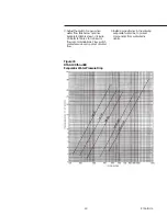
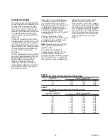
Water flow rates, as a function of
pressure drop, are charted in Figure 25,
or pressure drop can be calculated
using the following formula:
Pressure Drop (Ft. H20) = 2.31 (Drain
psig -Vent psig)
A pipe strainer should be installed in
the entering water line to prevent
waterborne debris from entering the
domestic water heater.
Domestic Water Heater
Piping Components
“Piping components” include all
devices and controls used to provide
proper water system operation and
unit operating safety. These
components and their general
locations are given below.
Entering Water Piping
[ ] Drain
[ ] Vibration eliminators.
[ ] Shutoff (isolation) valves.
[ ] Pipe strainer.
Caution: To prevent tube damage
install strainer in the water inlet
piping.
Leaving Chilled Water Piping
[ ] Air vents (to bleed air from system)
[ ] Vibration eliminators.
[ ] Shutoff (isolation) valves.
[ ] Balancing valve.
Caution: To prevent damage, do
not exceed 215 psig (14.6 bar)
domestic water heater water
pressure.
Water Pressure Relief Valves
Install a water pressure relief valve in
the outlet piping between the domestic
water heater and the outlet shutoff
valve, as shown in Figure 24. Water
vessels with close-coupled shutoff
valves have a high potential for
hydrostatic pressure buildup on a
water temperature increase. Refer to
applicable codes for relief valve
installation guidelines.
Caution: To prevent shell damage,
install pressure relief valves in the
evaporator water system.
Freeze Protection
If water in the domestic water heater
will be subjected to subfreezing
ambient temperatures, the water
system must be protected from
freezing, following the steps listed
below:
1. Heat tape is factory-installed on the
domestic water heater and will
protect it from freezing in ambient
temperatures down to -20 F Insure
that electrical power is provided for
the heat tape.
2. Install heat tape on all water piping,
pumps, and other components that
may be damaged if exposed to
freezing temperatures. Heat tape
must be designed for low ambient
temperature applications. Heat tape
selection should be based on the
lowest expected ambient
temperature.
Summary of Contents for RTAA-130
Page 2: ... American Standard Inc 1991 ...
Page 8: ...8 RTAA IOM 3 ...
Page 24: ...24 RTAA IOM 3 ...
Page 50: ...50 RTAA IOM 3 Figure 30 Refrigerant Circuit Identification ...
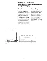
Page 52: ...52 RTAA IOM 3 Figure 31 Remote Evaporator Piping Example ...
Page 59: ...59 RTAA IOM 3 Continued from Previous Page See Notes on Next Page ...
Page 63: ...63 RTAA IOM 3 Continued from Previous Page See Notes on Page 61 ...
Page 65: ...65 RTAA IOM 3 Continued from Previous Page See Notes on Page 61 ...
Page 76: ...76 RTAA IOM 3 ...
Page 92: ...92 RTAA IOM 3 Figure 51 Operator Interface Controls ...
Page 120: ...120 RTAA IOM 3 ...
Page 127: ...127 RTAA IOM 3 Continued from Previous Page 2307 1566C ...
Page 128: ...128 RTAA IOM 3 Figure 57 Unit Sequence of Operation RTAA 130 to 200 Tons 2306 9122A ...
Page 132: ...132 RTAA IOM 3 Figure 58 Operator s Log ...
Page 138: ...138 RTAA IOM 3 ...


