


121
RTAA-IOM-3
Pre-Start
Checkout
General
When installation is complete, but prior
to putting the unit into service, the
following pre-start procedures must be
reviewed and verified correct:
[ ] Inspect all wiring connections to be
sure they are clean and tight.
WARNING: Disconnect all electric
power including remote
disconnects before servicing’
Failure to disconnect power
before servicing can cause severe
personal injury or death.
Caution: Check the tightness of all
connections in the compressor
power circuits (disconnects,
terminal block, contactors,
compressor junction box terminals,
etc.). Loose connections can cause
overheating at the connections and
undervoltage conditions at the
compressor motor.
[ ] Verify that all refrigerant valves, as
shown in Figure 37, are “OPEN”.
Caution: Do not operate the unit
with the compressor, oil discharge
and liquid line service valves
“CLOSED”. Failure to have these
“OPEN” may cause serious
compressor damage.
[ ] Check the power supply voltage to
the unit at the main power fused
disconnect switch. Voltage must be
within the voltage utilization range,
given in Table 10 and also stamped
on the unit nameplate. Voltage
imbalance must not exceed 2
percent. Refer to “Unit Voltage
Imbalance”, below.
WARNING: Disconnect all electric
power including remote
disconnects before servicing.
Failure to disconnect power
before servicing can cause severe
personal injury or death.
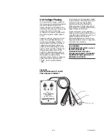
[ ] Check the unit power phasing to be
sure that it has been installed in an
“ABC” sequence. Refer to “Unit
Voltage Phasing”, below.
WARNING: It is imperative that
L1 -L2-L3 in the starter be
connected in the A-B-C phase
sequence to prevent equipment
damage due to reverse rotation.
[ ] Check the condenser fans to be sure
that they rotate freely in the fan
openings and that each is securely
attached to its fan motor shaft.
WARNING: Disconnect all electric
power Including remote
disconnects before servicing.
Failure to disconnect power
before servicing can cause severe
personal injury or death.
[ ] Energize the compressor sump
heaters by closing the unit main
disconnects. If unit-mounted
disconnects are used, they must
also be closed. If the unit does not
have the optional control power
transformer, 115 VAC power must
be field supplied to terminals 1TB3-1
AND 1TB3-2. The Chiller Switch
must be in the STOP/RESET
position.
Caution: The compressor sump
heaters must be energized for a
minimum of 24 hours prior to unit
operation, to prevent compressor
damage caused by liquid
refrigerant in the compressor at
start-up.
Summary of Contents for RTAA-130
Page 2: ... American Standard Inc 1991 ...
Page 8: ...8 RTAA IOM 3 ...
Page 24: ...24 RTAA IOM 3 ...
Page 50: ...50 RTAA IOM 3 Figure 30 Refrigerant Circuit Identification ...
Page 52: ...52 RTAA IOM 3 Figure 31 Remote Evaporator Piping Example ...
Page 59: ...59 RTAA IOM 3 Continued from Previous Page See Notes on Next Page ...
Page 63: ...63 RTAA IOM 3 Continued from Previous Page See Notes on Page 61 ...
Page 65: ...65 RTAA IOM 3 Continued from Previous Page See Notes on Page 61 ...
Page 76: ...76 RTAA IOM 3 ...
Page 92: ...92 RTAA IOM 3 Figure 51 Operator Interface Controls ...
Page 120: ...120 RTAA IOM 3 ...
Page 127: ...127 RTAA IOM 3 Continued from Previous Page 2307 1566C ...
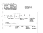
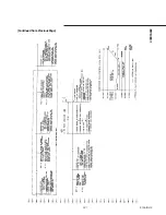
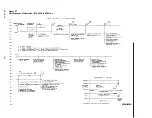
Page 128: ...128 RTAA IOM 3 Figure 57 Unit Sequence of Operation RTAA 130 to 200 Tons 2306 9122A ...
Page 132: ...132 RTAA IOM 3 Figure 58 Operator s Log ...
Page 138: ...138 RTAA IOM 3 ...


