40
OAU-SVX006E-EN
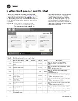
System Configuration and Pre-Start
The following procedure must be completed prior to
performing the startup procedure in
. This
section describes procedures to navigate the various
displays on the Unit Display and configure the Outdoor Air
Unit Main Unit Display system setpoints and operating
parameters.
Important:
This section is intended to provide
guidelines for navigation through the
remote operator display screens. For
additional control system information, refer
to
Integration Guide: Tracer™ UC600
Programmable Controller for Packaged
Outdoor Air Unit
(BAS-SVP18*-EN). The
unit is configured at the factory with the
default settings as described in
sequence of
operation and
the details concerning setup
and operating setpoints.
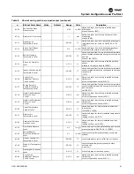
Table 8.
Chart of analog and binary input/output
#
BACnet Point Name
Write
Default
Range
Units
Description
AI-01
Space Temperature
Local
40–95
°F
Hardwired input from field installed space
temperature sensor, wired to OAUTS-1 & -2
(SPTC).
AI-02
Space Humidity Local
0–100
%
Hardwired input from field installed space humidity
sensor,
wired to OAUTS-5 & -6 (SPHC).
AI-03
Supply Fan Piezo
Pressure Local
0–25
in.H
2
O
Hardwired input from factory installed piezo
differential
pressure sensor (SPZ).
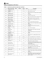
AI-04
Outdoor Coil Leaving
Temperature
Circuit 1 Local
-50–270
°F
Hardwired input from factory installed temperature
sensor
located on the outdoor coil (CCTC1).
AI-05
Outdoor Coil Leaving
Temperature
Circuit 2 Local
-50–270
°F
Hardwired input from factory installed temperature
sensor
located on the outdoor coil (CCTC2).
AI-06
Return Air Temperature
Local
-40–135
°F
Hardwired input from factory installed temperature
sensor
located in the return air path (RTC).
AI-07
Outdoor Air Damper
Position Status
Local
0-100
%
Hardwired input that provides feedback status
from the
actuator located on the outdoor air damper (OAD).
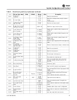
AI-08
Space CO
2
Concentration Local
-
ppm
Hardwired input from field provided CO2.

