TR - ELE - BA - GB - 0008 - 06 14.12.2007
User Manual
Laser Measuring Device LE-200 with Interbus-S - interface
●
Safety notes
Assembly
Installation / Commissioning
Parameter setting
Causes of Faults and Remedies
LE-200
Interbus-S
Page 1: ... BA GB 0008 06 14 12 2007 User Manual Laser Measuring Device LE 200 with Interbus S interface Safety notes Assembly Installation Commissioning Parameter setting Causes of Faults and Remedies LE 200 Interbus S ...
Page 2: ...ions is forbidden Reproduction translation as well as electronic and photographic archiving and modification require the written content of the manufacturer Offenders will be liable for damages Subject to amendments Any technical changes that serve the purpose of technical progress reserved Document information Release date Rev date 14 12 2007 Document rev no TR ELE BA GB 0008 06 File name TR ELE ...
Page 3: ...al page has its own revision status and date in the footer there may be different revision statuses within the document Documents that are in the appendix have their own revision history Document created 16 09 2003 Revision Date Revision of the warning label in chapter Intended purpose 18 12 2003 Modification of the Laser Standard DIN EN 60825 1 Warning bit Plausibility measured value Additional r...
Page 4: ...ectrical connection 17 5 1 1 Supply voltage 17 5 1 2 Interbus S 17 5 1 2 1 Remote IN 17 5 1 2 2 Remote OUT 18 5 1 2 3 Identification of following slaves 18 5 1 3 Switching input Switching output 18 5 1 4 RS485 programming interface 18 5 1 5 Wiring examples 19 5 2 Adjusting of the speed monitoring optional 20 5 3 Interbus S Interface 20 5 3 1 Mapping of Laser Data in the Master Controller 21 5 3 2 ...
Page 5: ...Function external output 32 6 2 12 Save parameters 33 7 Causes of Faults and Remedies 33 8 Maintenance 34 8 1 General Maintenance Information 34 8 2 Repair Maintenance 34 9 Appendix 35 9 1 Specifications 35 9 1 1 Electrical ratings 35 9 1 2 Environmental conditions 36 9 2 Ordering information 37 9 2 1 Laser devices 37 9 2 2 Accessories 37 Pin Assignment TR ELE TI GB 0008 Drawings Dimensioned drawi...
Page 6: ...malfunction code see page 27 It is therefore essential to integrate the malfunction code into your own safety system via the evaluation software e g a PLC All persons responsible for the assembly start up and operation of the device must be suitably qualified adhere strictly to this operating manual Your safety and the safety of your equipment depends on this 1 2 Safety information This operating ...
Page 7: ...reactivation of the equipment The safety and accident prevention regulations applicable to the specific application must be observed In the case of permanently installed plants or systems without an all pole mains switch and or fuses one of these devices must be installed accordingly and the equipment connected to a PE conductor In the case of 24 V supplies make sure the extra low voltage is relia...
Page 8: ... shield Avoid crossing cables where possible If unavoidable only cross them at right angles Ensure continuous wiring of the shield and a large contact area on special shield clampings or cable screw glands see Figure 1 point A and B RD BA U 1 20 X1 DIP Switch ON OFF 2 0 2 7 A B RC Figure 1 Connection cap with cable screw glands and shield clampings Shield connection via cable screw glands 1 Screw ...
Page 9: ...ying out wiring work or opening and closing electrical connections Short circuits voltage peaks etc can cause operating failures and uncontrolled operating states as well as serious personal injuries and damage to property Check all electrical connections before switching on the system Incorrectly wired connections can cause operating failures while wrong connections can lead to serious personal i...
Page 10: ... the blinking reflex for the protection of the eyes may not be assumed Therefore the eyes should be closed consciously or the head should be turned away immediately The device must be installed in such a way that the exposure of persons to the laser beam can only happen accidentally The laser beam may only extend as far as is necessary for the range measurement The beam must be limited at the end ...
Page 11: ...1 5 Safety measures at the installation site Warning Do not perform any welding work once the device is connected and switched on Variations in potential can destroy the device or restrict its operation Do not touch plug contacts with your hands Static charges may destroy electronic components of the device Do not connect unused inputs see pin assignment Observe the voltage supply range Standard d...
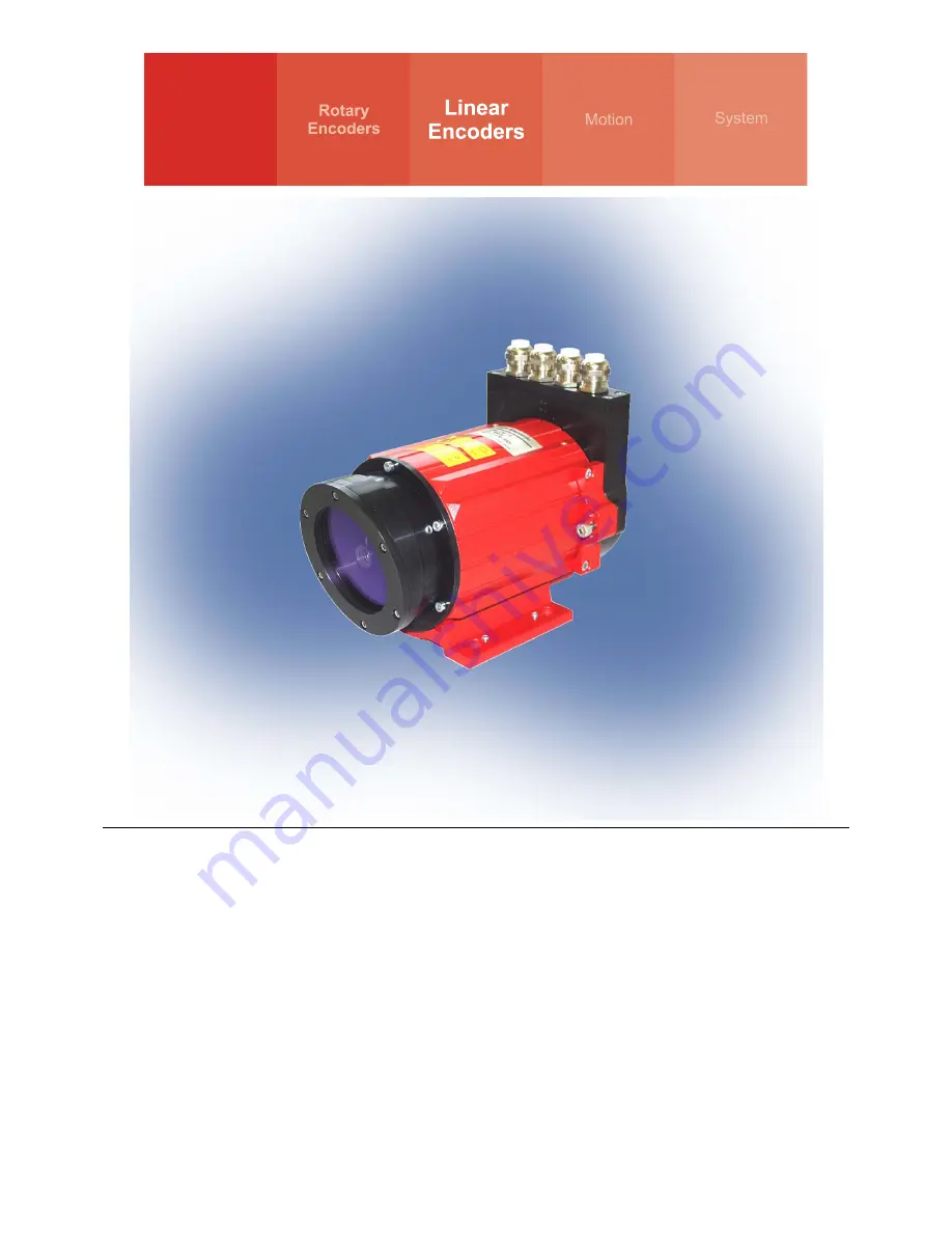
Page 12: ...l as a reflector The device sends out a modulated light beam which is reflected by the reflector From the phase difference of the sent and received light beam the distance is measured 1000 times per second Thus the LE is suitable also directly for the position feedback in controller loops According to the requirements the laser distance measuring devices of the series LE 200 Interbus S are configu...
Page 13: ... 13 of 37 3 Transportation Storage Transport instructions Do not drop the device or expose it to shocks or vibrations Device contains an optical system with glass elements Only use the original packaging The wrong packaging material can cause damage to the device during transportation Storage Storage temperature 20 to 75 C Store in dry conditions ...
Page 14: ...ed to the moving object and the reflector sensor to the fixed remote station in such a way that the reflector always remains within the visual field of the sensor This can be done using the light spot of the laser diode which is still clearly visible on the reflecting foil even at long distance When aligning the laser measuring device the user may need to take measures to ensure that it can be mec...
Page 15: ... angle of incidence angle of reflection Figure 4 Transmitting away the surface reflectivity Rotate the reflector foil in the Y or in the Z axis so that the interference signal B always is outside the laser lens Nevertheless keeping the inclination of the reflector foil as low as possible to minimize measuring errors caused by misalignments in the procedure movement For example if the light spot dr...
Page 16: ...f laser linear paths It has to be taken care in the parallel operation of laser linear paths that a minimum distance of 1 m is kept The reflector foil inclination must be made in such a way that the surface reflectivity see arrows points not into the other laser linear path The alignment is carried out as described in chapter 4 4 1 Figure 5 Minimum distance in parallel operation ...
Page 17: ...out the connection the connection cap must be removed from the laser first For this the screws A are loosened and the cap B is removed away from the laser A B A RD BA U 1 20 X1 DIP Switch ON OFF 2 0 2 7 RC 5 1 1 Supply voltage Pin 7 0V GND Pin 8 Standard 18 27 V DC Device with heating 24 V DC 5 1 2 3 4 5 6 7 8 9 10 11 121314 1516171819 20 5 1 2 Interbus S 5 1 2 1 Remote IN Pin 15 GNDI reference po...
Page 18: ...ried out either directly via the bus or via the PC software TRWinProg Functions of the switching input Preset Switch off laser diode Failure quit Functions of the switching output Temperature Intensity Hardware Fail Output every fail Speed check Plausibility measured value Switching output position Pin 1 GND reference potential pin 2 Pin 2 Switching output Pin 3 Switching input 1 2 3 4 5 6 7 8 9 1...
Page 19: ... Wiring examples Shield connection see chapter 1 2 1 1 page 8 Interbus S connection 7 8 15 16 17 18 19 20 0V Supply Voltage GNDI Shield DO1 DO1 DI1 DI1 LE 200 0V US X1 14 13 12 11 5 6 4 DI2 DI2 DO2 DO2 RBST GND GND DI1 DI1 DO1 GNDI DO1 REMOTE IN Jumper for the identification that a further slave is following X1 RS485 connection with parameter setting via TRWinProg ...
Page 20: ...e with 32 I O data This makes it easy to integrate in the bus ring in the same way as a PHOENIX CONTACT bus terminal To ensure that the protocol meets INTERBUS S requirements an SUPI serial microprocessor interface is integrated between the LE 200 and the INTERBUS S The SUPI is an INTERBUS S protocol chip developed by PHOENIX CONTACT which carries out the following functions BUS interfacing Direct...
Page 21: ... 0 AV PA X P4 P3 P2 P1 Return Parameter Value 25 bit B15 B14 B13 B12 B11 B10 B9 B8 B7 B6 B5 B4 B3 B2 B1 B0 2 31 2 30 2 29 2 28 2 27 2 26 2 25 2 24 2 23 2 22 2 21 2 20 2 19 2 18 2 17 2 16 2 15 2 14 2 13 2 12 2 11 2 10 2 9 2 8 2 7 2 6 2 5 2 4 2 3 2 2 2 1 2 0 Input byte x 0 Input byte x 1 Input byte x 2 Input byte x 3 AV Invalid position actual value PA Parameterization X not used P1 P4 Return parame...
Page 22: ...eserved 17 2 Reserved 18 3 Reserved 19 4 Reserved 20 5 Reserved 21 6 Reserved 22 7 Reserved 23 8 Reserved 24 9 Parameter no X 25 10 Parameter no X 26 11 Parameter no X 27 12 Parameter no X 28 13 Manufacturer specific 29 14 Set zero shift X 30 15 Enable operation X 31 see page 23 Set zero shift Device Control Commands The device control commands are triggered by the following bit combinations in th...
Page 23: ...meter data will transfer via the bits 0 to 24 of the process out data channel The activation of parameter transfer is receipted within a second in the status word Set zero shift If in parameter no 1101 is programmed the value 0 not clear an edge change of 0 to 1 of the bit no 30 in the process out data channel is setting the laser to the preselected value in parameter no 0100 see also Parameter ov...
Page 24: ...erved 19 4 Reserved 20 5 Reserved 21 6 Reserved 22 7 Reserved 23 8 Reserved 24 9 Parameter no or malfunction code X 25 10 Parameter no or malfunction code X 26 11 Parameter no or malfunction code X 27 12 Parameter no or malfunction code X 28 13 Manufacturer specific 29 14 Parameterization X 30 15 Invalid position actual value X 31 Device States The device states are shown in the status word by the...
Page 25: ...ser is acknowledged via bits 9 to 12 or a malfunction code is transmitted in malfunction state see page 27 Manufacturer Specific Bits 0 8 are reserved Bit 13 is manufacturer specific 5 3 4 Bus status At the connection cap the laser has 4 LEDs which display the bus status of the laser RD BA U RC RD red Following IBS Interface is disconnected or bus communication disturbed U green SUPI Supply Voltag...
Page 26: ...the process out data channel of the master to the laser To this the laser must be set to the parameterization state This is achieved by outputting a parameter number unequal to zero on bits 9 to 12 of the control word bits 25 to 28 of the process out data channel Parameter overview Parameter No B12 B9 Function 0 0 0 0 Output in operation state 0 0 0 1 Resolution 0 10 mm 1 1 mm 2 0 1 mm 3 0 01 mm 4...
Page 27: ...mission of the parameter with the return of the corresponding parameter number The new parameter takes effect after the user has set the laser to the operation state with the enable operation device control command If it was not possible for the parameter to take effect the laser switches over to the malfunction state after the user has sent the enable operation device control command and outputs ...
Page 28: ...meter 1 1 P No Parameter Processing of parameter is comple ted Laser remains in parameteriza tion state 7 1 0 0 1 1 P No Parameter Device control command enable operation from host to the laser Laser does not yet react 8 1 0 0 0 0 0 Actual value Laser once more in operation state 9 0 0 0 0 0 0 Actual value Normal operating mode once more reached by both devices 1 You must make sure that when a par...
Page 29: ...to the Laser 8 0 8 1 1 1 1 5 Host continues to wait for acknowledgement from laser 9 0 8 1 1 1 8 1 Processing of parameter is completed Laser remains in parameterization state 10 1 0 0 1 1 8 1 Device control command enable operation from host to the laser Laser does not yet react 11 1 0 0 0 1 1 Actual value Laser switches to malfunction state the malfunction code is 1 The position actual value is ...
Page 30: ...1 Inch 0 5 1 6 2 2 Switching off laser diode For increase the life time of the laser diode the laser diode can be switched inactively with transmission of this parameter no If in parameter no 1100 Function external input page 32 the parameter value 2 Switch off laser diode was programmed or the parameter 0101 Switch off laser diode automatic if Interbus S is inactive page 31 is active this paramet...
Page 31: ...parameter no 1100 Function external input page 32 the parameter value 2 Switch off laser diode was programmed this parameter is ineffective Parameter No B12 B9 Parameter value in D0 D24 Value range Default 0 1 0 1 0 disabled 1 active 0 1 0 6 2 6 Counting direction Determination of the measuring system counting direction Parameter No B12 B9 Parameter value in D0 D24 Value range Default 1 0 0 0 0 wi...
Page 32: ...ers the switching off of the laser diode is carried out automatically the LD switching input does not have a function Parameter No B12 B9 Parameter value in D0 D24 Value range Default 1 1 0 0 0 disabled 1 Preset 2 Switch off laser diode 3 Failure quit 0 3 0 6 2 10 Clear Preset Via this parameter the zero point correction calculated under the parameter Preset preselection 0100 is deleted The correc...
Page 33: ...e replaced 1001 Intensity warning The device deter mined an intensity of 12 This message is only a warning and means that the measuring system optics or the reflecting foil is to be cleaned However the device operates error freely furthermore 1010 Laser diode switched off The bit is set if the laser diode was switched off over the bus or the switching input Serves only for information purposes 110...
Page 34: ...re maintenance by the operator Note If the lens opening of the laser or the reflecting foil become dirty clean with a soft cloth Do not use an aggressive cleaning material such as thinner or acetone 8 2 Repair Maintenance Repairs to the devices must only be carried out by the manufacturer Contact your TR Electronic GmbH distributor or service organisation should repairs be required The addresses a...
Page 35: ...aser power P 1 mW Laser protection class 2 according to DIN EN 60 825 1 2003 10 Lifetime 50 000 h Measured value output refresh cycle 1000 values s Integration time 1 ms Reproducibility 2 mm Programming via RS485 PC IBM compatible TRWinProg Interbus S Interbus S Interface Interbus S according to DIN 19258 Two wire remote bus for transmission and receive direction RS422 with galvanic isolation Prof...
Page 36: ...ature range 0 50 C Device with heating 30 to 50 C Thermal drift 1 ppm C related to the max measuring length of 125 m 170 m 195 m or 240 m Storage temperature range 20 to 75 C Relative air humidity 98 no moisture condensation Degree of protection IP 65 DIN 40 050 Vibration 50 2000 Hz Sinusoidal DIN IEC 68 2 6 50 m s2 5g Shock 11ms DIN IEC 68 2 27 300 m s2 30g The protection class is valid for the d...
Page 37: ...T 15 2 switch cabinet module for PC adapter connection 490 00310 Device PC adapter RS485 USB 490 01001 Soft No 490 00416 TRWinProg PC software with user manual German and English Reflecting foils for measurements up to 125m 49 500 020 200 x 200 mm package contents 49 500 038 200 x 300 mm 49 500 031 749 x 914 mm Other sizes upon request In addition the foils can be sticked on side by side up to the...