2GR-FE STARTING
– SMART KEY SYSTEM
ST–11
ST
SYSTEM DESCRIPTION
1.
PUSH-BUTTON START FUNCTION DESCRIPTION
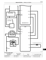
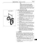
(a) The push-button start function uses a push-type
engine switch, which the driver can operate by
merely carrying the electrical key. This system
consists primarily of the main body ECU, engine
switch, ID code box, steering lock ECU, electrical
key, ACC relay, IG1 relay, IG2 relay and certification
ECU. The main body ECU controls the function.
This function operates in cooperation with the smart
key system.
2.
FUNCTION OF COMPONENT
3.
SYSTEM FUNCTION
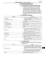
The electric controls of the push-button start function are
described below:
Component
Function
Engine Switch
•
Transponder Key Amplifier
•
Transmits engine switch signal to main body ECU.
•
Informs driver of power source mode or system abnormality with
illumination of indicator light.
•
Receives ID code and transmits it to certification ECU when key
battery is low.
Electrical Key
Receives signals from oscillators and returns ID code to entry door
control receiver.
Electrical Key Oscillator
•
Console and Rear Seat
Receives request signals from certification ECU and forms detection
area in vehicle interior.
Steering Lock ECU
Receives lock/unlock request signals from certification ECU and main
body ECU.
Entry Door Control Receiver
Receives ID code from electrical key and transmits it to certification
ECU.
Main body ECU
•
Changes power source mode in 4 stages (off, on (ACC), on (IG),
start) in accordance with shift position and state of stop light
switch.
•
Controls push-button start function in accordance with signals
received from switches and each ECU.
Certification ECU
Certifies ID code received from entry door control receiver and
transmits certification results to ID code ECU and steering lock ECU.
Stop Light Switch
Outputs state of brake pedal to main body ECU.
ID Code Box
Receives steering unlock or engine immobiliser unset signals from
certification ECU, certifies them, and transmits each unset signal to
steering lock ECU or ECM.
ECM
•
Receives engine start request signal from main body ECU, turns
ON ST relay, and starts engine.
•
Receives signal from ID code ECU and performs engine ignition
and injection.
Control
Outline
Engine switch control
•
When driver operates engine switch with electrical key in driver's
possession, certification ECU starts indoor electrical key oscillator,
which transmits request signal to electrical key. Upon receiving
this signal, the electrical key transmits ID code signal to main body
ECU.
•
ID code box verifies check results received from certification ECU
via LIN and sends them to main body ECU. Based on these
results, main body ECU authorizes operation of engine switch.
Diagnosis
When main body ECU detects malfunction, main body ECU
diagnoses and memorizes failed section.
Summary of Contents for 2GR-FE
Page 176: ...ES 20 2GR FE ENGINE CONTROL SYSTEM SFI SYSTEM ES NEXT 20 CONDUCT CONFIRMATION TEST END ...
Page 247: ...2GR FE ENGINE CONTROL SYSTEM SFI SYSTEM ES 91 ES OK REPLACE ECM See page ES 518 ...
Page 412: ...ES 256 2GR FE ENGINE CONTROL SYSTEM SFI SYSTEM ES A END ...
Page 447: ...2GR FE ENGINE CONTROL SYSTEM SFI SYSTEM ES 291 ES OK REPLACE ECM See page ES 518 ...
Page 556: ...ES 400 2GR FE ENGINE CONTROL SYSTEM SFI SYSTEM ES A REPLACE TCM ...
Page 630: ...ES 474 2GR FE ENGINE CONTROL SYSTEM SFI SYSTEM ES OK REPLACE ECM See page ES 518 ...
Page 658: ...2GR FE ENGINE CONTROL SYSTEM VVT SENSOR ES 493 ES 22 INSTALL ENGINE UNDER COVER LH ...
Page 897: ...2GR FE STARTING SMART KEY SYSTEM ST 35 ST OK REPLACE MAIN BODY ECU ...
Page 923: ...2GR FE STARTING SMART KEY SYSTEM ST 61 ST OK REPLACE MAIN BODY ECU ...
Page 935: ...2GR FE STARTING SMART KEY SYSTEM ST 73 ST OK REPLACE MAIN BODY ECU ...
Page 940: ...ST 78 2GR FE STARTING SMART KEY SYSTEM ST OK REPLACE MAIN BODY ECU ...
Page 958: ...ST 96 2GR FE STARTING SMART KEY SYSTEM ST OK END MAIN BODY ECU DEFECTIVE ...


