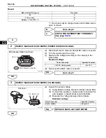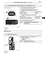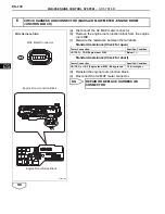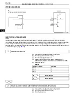
2GR-FE ENGINE CONTROL SYSTEM
– SFI SYSTEM
ES–145
ES
HINT:
When any of these DTCs are set, check the IAT by entering the following menus on the intelligent tester:
DIAGNOSIS / ENHANCED OBD II / DATA LIST / PRIMARY / INTAKE AIR.
MONITOR DESCRIPTION
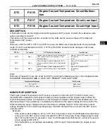
The ECM monitors the sensor voltage and uses this value to calculate the Intake Air Temperature (IAT).
When the sensor output voltage deviates from the normal operating range, the ECM interprets this as a
malfunction in the IAT sensor and sets a DTC.
Example:
If the sensor output voltage is -40
°
C (-40
°
F) for 0.5 seconds or more, the ECM determines that there is
an open in the IAT sensor circuit, and sets DTC P0113. Conversely, if the output voltage is more than
140
°
C (284
°
F) for 0.5 seconds or more, the ECM determines that there is a short in the sensor circuit,
and sets DTC P0112.
If the malfunction is not repaired successfully, a DTC is set 0.5 seconds after the engine is next started.
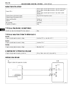
MONITOR STRATEGY
TYPICAL ENABLING CONDITIONS
TYPICAL MALFUNCTION THRESHOLDS
P0110:
P0112:
P0113:
COMPONENT OPERATING RANGE
Temperature Displayed
Malfunction
-40
°
C (-40
°
F)
Open circuit
140
°
C (284
°
F) or higher
Short circuit
Related DTCs
P0110: Intake air temperature sensor open/short (Fluctuating)
P0112: Intake air temperature sensor short (Low electrical resistance)
P0113: Intake air temperature sensor open (High electrical resistance)
Required Sensors/Components (Main)
Intake Air Temperature (IAT) sensor
Required Sensors/Components (Sub)
-
Frequency of Operation
Continuous
Duration
0.5 seconds
MIL Operation
Immediate
Sequence of Operation
None
Monitor runs whenever following DTCs are not present
None
Intake air temperature sensor voltage
Less than 0.18 V, or more than 4.91 V
Intake air temperature sensor voltage
Less than 0.18 V
Intake air temperature sensor voltage
More than 4.91 V
Intake air temperature sensor resistance
98.5
Ω
to 156 k
Ω
[-40 to 140
°
C (-40 to 284
°
F)]
Summary of Contents for 2GR-FE
Page 176: ...ES 20 2GR FE ENGINE CONTROL SYSTEM SFI SYSTEM ES NEXT 20 CONDUCT CONFIRMATION TEST END ...
Page 247: ...2GR FE ENGINE CONTROL SYSTEM SFI SYSTEM ES 91 ES OK REPLACE ECM See page ES 518 ...
Page 412: ...ES 256 2GR FE ENGINE CONTROL SYSTEM SFI SYSTEM ES A END ...
Page 447: ...2GR FE ENGINE CONTROL SYSTEM SFI SYSTEM ES 291 ES OK REPLACE ECM See page ES 518 ...
Page 556: ...ES 400 2GR FE ENGINE CONTROL SYSTEM SFI SYSTEM ES A REPLACE TCM ...
Page 630: ...ES 474 2GR FE ENGINE CONTROL SYSTEM SFI SYSTEM ES OK REPLACE ECM See page ES 518 ...
Page 658: ...2GR FE ENGINE CONTROL SYSTEM VVT SENSOR ES 493 ES 22 INSTALL ENGINE UNDER COVER LH ...
Page 897: ...2GR FE STARTING SMART KEY SYSTEM ST 35 ST OK REPLACE MAIN BODY ECU ...
Page 923: ...2GR FE STARTING SMART KEY SYSTEM ST 61 ST OK REPLACE MAIN BODY ECU ...
Page 935: ...2GR FE STARTING SMART KEY SYSTEM ST 73 ST OK REPLACE MAIN BODY ECU ...
Page 940: ...ST 78 2GR FE STARTING SMART KEY SYSTEM ST OK REPLACE MAIN BODY ECU ...
Page 958: ...ST 96 2GR FE STARTING SMART KEY SYSTEM ST OK END MAIN BODY ECU DEFECTIVE ...


