FU-3
FUEL SYSTEM Description
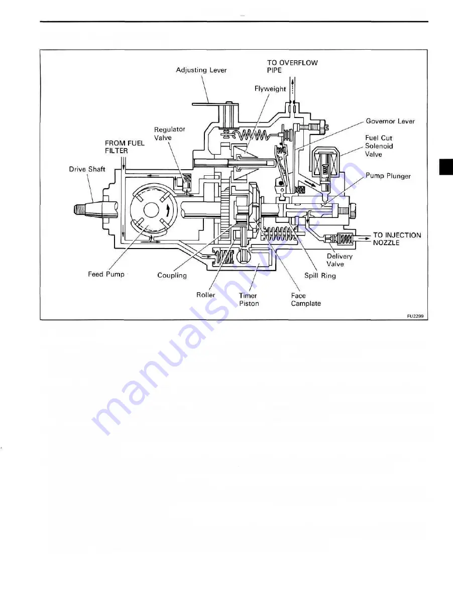
Injection Pump (VE Pump)
OPERATION
• The centrifugal force type feed pump takes up a fixed volume of fuel with each turn. The fuel expulsion
pressure from the feed pump is controlled by operation of the pressure regulator valve.
• Fuel is sent from the outlet side of the feed pump, through the hole in the upper part of the feed pump cover
and into the pump body.
• The pump plunger also rotates as it moves up and down. After the fuel is drawn in, it is distributed under
pressure to the delivery valve of each cylinder according to the injection order.
• The centrifugal force type all speed governor installed in the upper part of the injection pump moves the spill
ring obstructing the plunger spill port and controls the fuel injection volume.
• The hydraulic type timer installed in the lower part of the injection pump is operated by the fuel pressure of
the pump housing, and movement of the roller ring by the timer advances the injection angle and controls
the injection timing.
• The fuel cut solenoid valve is connected to the starter switch IG circuit, and when the starter switch is turned
to OFF, the current is cut off, the solenoid is de-energized, fuel is cut off and the engine stops.
• High Altitude Compensation (HAC) Device
Due to the decrease in atmospheric pressure at high altitudes, the air fuel ratio becomes more dense and the
smoke density increases. To prevent this, the device automatically reduces the fuel injection volume for full
loads in response to the altitude.
• Boost Compensator with turbocharger
The boost compensator is installed on the upper part of the governor of the injection pump. Turbocharged
air pressure moves the diaphragm and push rod up and down, this movement is conveyed to the spill ring
and the fuel injection volume increases according to the degree of movement.
Summary of Contents for 1HD-T
Page 1: ......
Page 53: ...EM 42 ENGINE MECHANICAL Timing Gears TIMING GEARS COMPONENTS ...
Page 65: ...EM 54 ENGINE MECHANICAL Cylinder Head CYLINDER HEAD COMPONENTS ...
Page 95: ...EM 84 ENGINE MECHANICAL Cylinder Block CYLINDER BLOCK COMPONENTS ...
Page 133: ...TURBOCHARGER SYSTEM Turbocharger TC 9 COMPONENTS ...
Page 145: ...FU 6 FUEL SYSTEM Fuel Heater System FUEL HEATER SYSTEM SYSTEM CIRCUIT ...
Page 166: ...FUEL SYSTEM Injection Pump FU 27 INJECTION PUMP REMOVAL OF INJECTION PUMP ...
Page 169: ...FU 30 FUEL SYSTEM Injection Pump COMPONENTS ...
Page 170: ...FUEL SYSTEM Injection Pump FU 31 COMPONENTS Cont d ...
Page 171: ...FU 32 FUEL SYSTEM Injection Pump COMPONENTS Cont d ...
Page 251: ...LU 4 LUBRICATION SYSTEM Troubleshooting TROUBLESHOOTING ...
Page 255: ...LU 8 LUBRICATION SYSTEM Oil Pump OIL PUMP COMPONENT ...
Page 272: ...ST 4 STARTING SYSTEM Pre Heating System Super Glow Type TIMER CHARACTERISTIC DIAGRAM Cont d ...
Page 282: ...ST 14 STARTING SYSTEM Starting System Circuit STARTING SYSTEM CIRCUIT Cont d ...
Page 340: ...B 1 STANDARD BOLT TORQUE SPECIFICATIONS Page STANDARD BOLT TORQUE SPECIFICATIONS B 2 ...
Page 343: ...C 1 SSTAND SSM Page SST SPECIAL SERVICE TOOLS C 2 SSM SPECIAL SERVICE MATERIALS C 6 ...


