CH-7
CHARGING SYSTEM - On-Vehicle Inspection
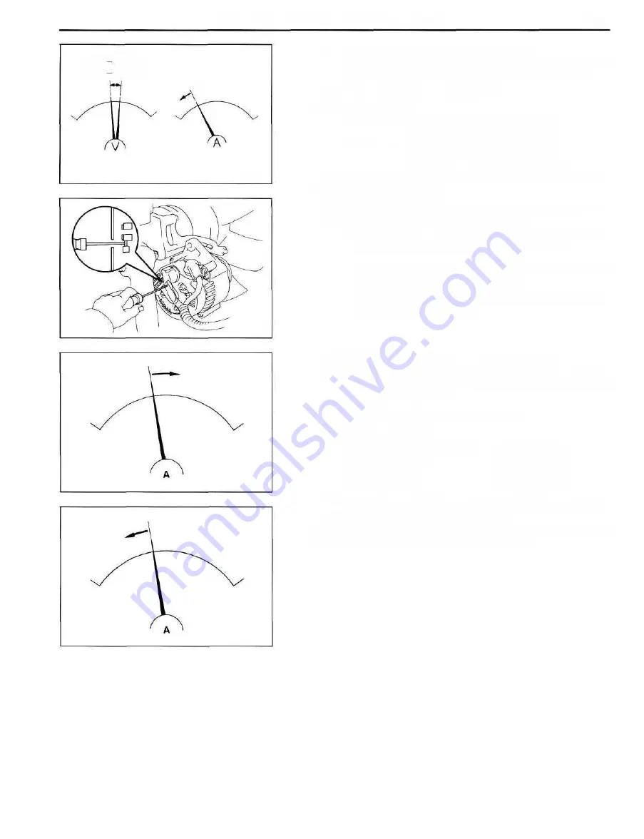
(b) Check the charging circuit as follows:
With the engine running from idling to 2,000 rpm,
check the reading on the ammeter and voltmeter.
Standard amperage: 10 A or less
Standard voltage:
12 V type 14.0-15.0 V at 25°C (77°F)
13.5-14.3 V at 135°C (275° F)
24 V type 27.7-28.7 V at 25°C (77°F)
26.0-28.7 V at 135°C (275°F)
If the voltmeter reading is more than standard voltage,
replace the IC regulator.
If the voltmeter reading is less than standard voltage, check
the IC regulator and alternator as follows:
• With terminal F grounded, start the engine and
check the voltmeter reading of terminalB.
• If the voltmeter reading is greater than standard ,
voltage, replace the IC regulator.
• If the voltmeter reading is less than standard volt-
age, check the alternator.
7. INSPECT CHARGING CIRCUIT WITH LOAD
(a) With the engine running at 2,000 rpm, turn on the
high beam headlights and place the heater blower
switch at "HI".
(b) Check the reading on the ammeter.
Standard amperage:
12 V 45, 55, 60, 80 A type 30 A or more
12 V 100 A type 40 A or more
24 V 30 A type 15 A or more
24 V 55 A type 30 A or more
If the ammeter reading is less than standard amperage,
repair the alternator. (See page CH-8)
HINT: With the battery fully charged, the indication will
sometimes be less than standard amperage.
26.0
13.5
28.7
V
15.0V
10 A
CH0704
CH0894
CH0838
CH0839
Summary of Contents for 1HD-T
Page 1: ......
Page 53: ...EM 42 ENGINE MECHANICAL Timing Gears TIMING GEARS COMPONENTS ...
Page 65: ...EM 54 ENGINE MECHANICAL Cylinder Head CYLINDER HEAD COMPONENTS ...
Page 95: ...EM 84 ENGINE MECHANICAL Cylinder Block CYLINDER BLOCK COMPONENTS ...
Page 133: ...TURBOCHARGER SYSTEM Turbocharger TC 9 COMPONENTS ...
Page 145: ...FU 6 FUEL SYSTEM Fuel Heater System FUEL HEATER SYSTEM SYSTEM CIRCUIT ...
Page 166: ...FUEL SYSTEM Injection Pump FU 27 INJECTION PUMP REMOVAL OF INJECTION PUMP ...
Page 169: ...FU 30 FUEL SYSTEM Injection Pump COMPONENTS ...
Page 170: ...FUEL SYSTEM Injection Pump FU 31 COMPONENTS Cont d ...
Page 171: ...FU 32 FUEL SYSTEM Injection Pump COMPONENTS Cont d ...
Page 251: ...LU 4 LUBRICATION SYSTEM Troubleshooting TROUBLESHOOTING ...
Page 255: ...LU 8 LUBRICATION SYSTEM Oil Pump OIL PUMP COMPONENT ...
Page 272: ...ST 4 STARTING SYSTEM Pre Heating System Super Glow Type TIMER CHARACTERISTIC DIAGRAM Cont d ...
Page 282: ...ST 14 STARTING SYSTEM Starting System Circuit STARTING SYSTEM CIRCUIT Cont d ...
Page 340: ...B 1 STANDARD BOLT TORQUE SPECIFICATIONS Page STANDARD BOLT TORQUE SPECIFICATIONS B 2 ...
Page 343: ...C 1 SSTAND SSM Page SST SPECIAL SERVICE TOOLS C 2 SSM SPECIAL SERVICE MATERIALS C 6 ...


