CH-5
CHARGING SYSTEM On-Vehicle Inspection
ON-VEHICLE INSPECTION
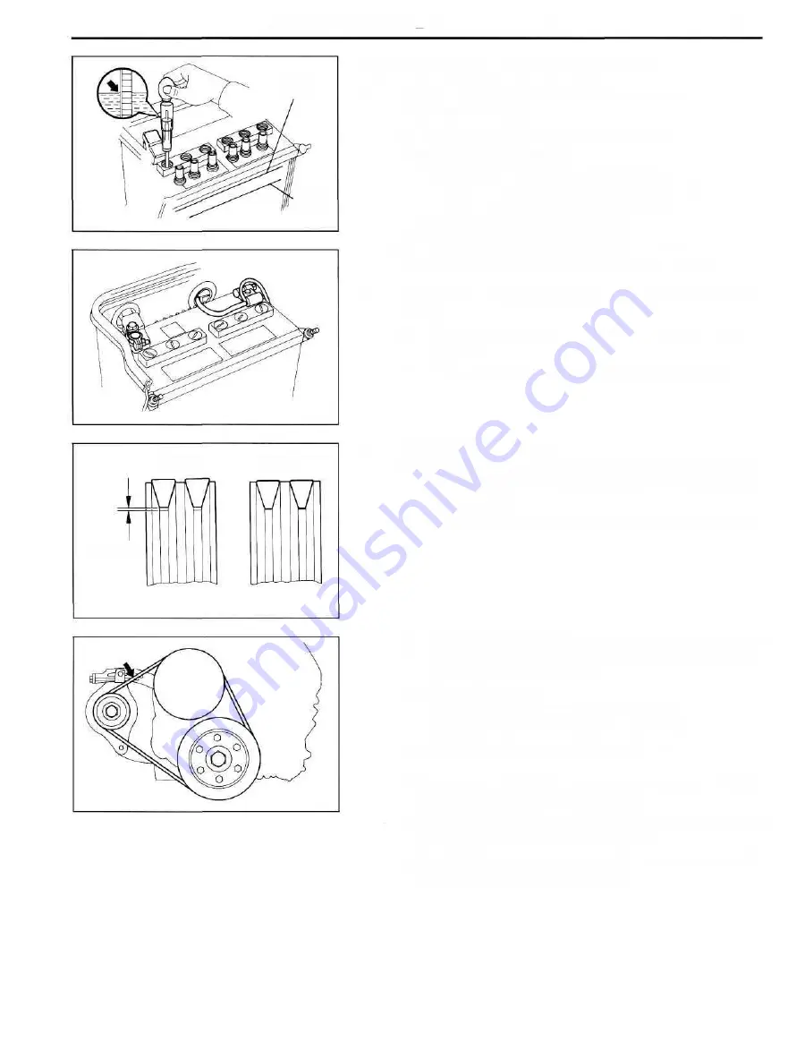
1. INSPECT BATTERY SPECIFIC GRAVITY AND
ELECTROLYTE LEVEL
(a) Check the specific gravity of each cell.
Standard specific gravity:
When fully charged at 20°C (68°F)
1.25-1.27 (ex. (95D31 R and 95D31L))
1.27 -1.29 (95D31R and 95D31L)
If not as specified, charge the battery.
(b) Check the electrolyte quantity of each cell.
If insufficient, refill with distilled (or purified) water.
2. CHECK BATTERY TERMINALS, FUSIBLE LINKS AND
FUSES
(a) Check that the battery terminals are not loose or
corroded.
(b) Check the fusible links and fuses for continuity.
3. INSPECT DRIVE BELTS
(a) Visually check each belt for cracks, oiliness or wear.
Check that the belt does not touch the bottom of the
pulley groove.
If one belt has any of the above defects, replace both belts.
(b) Check the drive belt deflection by pressing on the belt
at the points indicated in the illustration with 10 kg
(22.0 Ib, 98 N) of pressure.
Drive belt deflection:
New belt 6 - 7 mm (0.24-0.28 in.)
Used belt 8-11 mm (0.31 -0.43 in.)
If the deflection is not as specified, adjust it.
HINT:
• "New belt" refers to a belt which has been used 5
minutes or less on a running engine.
• "Used belt" refers to a belt which has been used on a
running engine for 5 minutes or more.
• After installing a new belt, run the engine for about 5
minutes and recheck the deflection.
Upper
Level
Lower
Level
CH0864
CH0865
CORRECT
WRONG
Clearance
CH0872
CH0866
Summary of Contents for 1HD-T
Page 1: ......
Page 53: ...EM 42 ENGINE MECHANICAL Timing Gears TIMING GEARS COMPONENTS ...
Page 65: ...EM 54 ENGINE MECHANICAL Cylinder Head CYLINDER HEAD COMPONENTS ...
Page 95: ...EM 84 ENGINE MECHANICAL Cylinder Block CYLINDER BLOCK COMPONENTS ...
Page 133: ...TURBOCHARGER SYSTEM Turbocharger TC 9 COMPONENTS ...
Page 145: ...FU 6 FUEL SYSTEM Fuel Heater System FUEL HEATER SYSTEM SYSTEM CIRCUIT ...
Page 166: ...FUEL SYSTEM Injection Pump FU 27 INJECTION PUMP REMOVAL OF INJECTION PUMP ...
Page 169: ...FU 30 FUEL SYSTEM Injection Pump COMPONENTS ...
Page 170: ...FUEL SYSTEM Injection Pump FU 31 COMPONENTS Cont d ...
Page 171: ...FU 32 FUEL SYSTEM Injection Pump COMPONENTS Cont d ...
Page 251: ...LU 4 LUBRICATION SYSTEM Troubleshooting TROUBLESHOOTING ...
Page 255: ...LU 8 LUBRICATION SYSTEM Oil Pump OIL PUMP COMPONENT ...
Page 272: ...ST 4 STARTING SYSTEM Pre Heating System Super Glow Type TIMER CHARACTERISTIC DIAGRAM Cont d ...
Page 282: ...ST 14 STARTING SYSTEM Starting System Circuit STARTING SYSTEM CIRCUIT Cont d ...
Page 340: ...B 1 STANDARD BOLT TORQUE SPECIFICATIONS Page STANDARD BOLT TORQUE SPECIFICATIONS B 2 ...
Page 343: ...C 1 SSTAND SSM Page SST SPECIAL SERVICE TOOLS C 2 SSM SPECIAL SERVICE MATERIALS C 6 ...


