EM-104
ENGINE MECHANICAL - Cylinder Block
INSPECTION AND REPAIR OF CRANKSHAFT
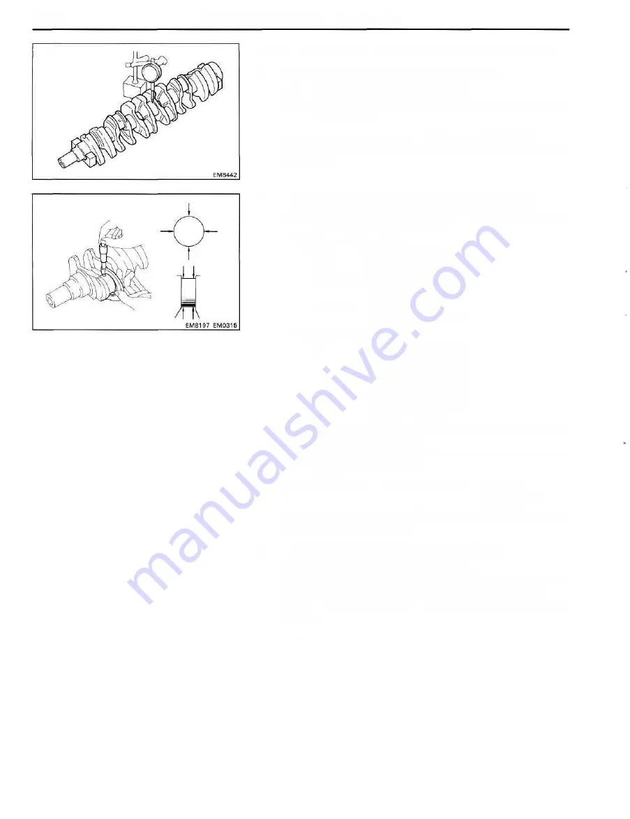
1. INSPECT CRANKSHAFT FOR RUNOUT
(a) Place the crankshaft on V-blocks.
(b) Using a dial indicator, measure the circle runout at the
center journal.
Maximum circle runout: 0.06 mm (0.0024 in.)
If the circle runout is greater than maximum, replace the
crankshaft.
2. INSPECT MAIN JOURNALS AND CRANK PINS
(a) Using a micrometer, measure the diameter of each
main journal and crank pin.
Main journal diameter:
STD 66.982-67.000 mm
(2.6371 -2.6378 in.)
U/S 0.25 66.745 - 66.755 mm
(2.6278-2.6281 in.)
U/S 0.50 66.495 - 66.505 mm
(2.6179-2.6183 in.)
Crank pin diameter:
STD 58.982-59.000 mm
(2.3221-2.3228 in.)
U/S 0.25 58.745-58.755 mm
(2.3128-2.3132 in.)
U/S 0.50 58.495-58.505 mm
(2.3029-2.3033 in.)
If the diameter is not as specified, check the oil clearance
(See pages EM-86 to 92).
(b) Check each main journal and crank pin for taper and
out-of-round as shown.
Maximum taper and out-of-round: 0.02 mm
(0.0008 in.)
If the taper or out-of-round is greater than maximum, grind
or replace the crankshaft.
3. IF NECESSARY, GRIND AND HONE MAIN
JOURNALS AND/OR CRANK PINS
Grind and hone the main journals and/or crank pins to the
finished undersized diameter (See procedure step 2).
Install new main journal and/or crank pin undersized
bearings.
Summary of Contents for 1HD-T
Page 1: ......
Page 53: ...EM 42 ENGINE MECHANICAL Timing Gears TIMING GEARS COMPONENTS ...
Page 65: ...EM 54 ENGINE MECHANICAL Cylinder Head CYLINDER HEAD COMPONENTS ...
Page 95: ...EM 84 ENGINE MECHANICAL Cylinder Block CYLINDER BLOCK COMPONENTS ...
Page 133: ...TURBOCHARGER SYSTEM Turbocharger TC 9 COMPONENTS ...
Page 145: ...FU 6 FUEL SYSTEM Fuel Heater System FUEL HEATER SYSTEM SYSTEM CIRCUIT ...
Page 166: ...FUEL SYSTEM Injection Pump FU 27 INJECTION PUMP REMOVAL OF INJECTION PUMP ...
Page 169: ...FU 30 FUEL SYSTEM Injection Pump COMPONENTS ...
Page 170: ...FUEL SYSTEM Injection Pump FU 31 COMPONENTS Cont d ...
Page 171: ...FU 32 FUEL SYSTEM Injection Pump COMPONENTS Cont d ...
Page 251: ...LU 4 LUBRICATION SYSTEM Troubleshooting TROUBLESHOOTING ...
Page 255: ...LU 8 LUBRICATION SYSTEM Oil Pump OIL PUMP COMPONENT ...
Page 272: ...ST 4 STARTING SYSTEM Pre Heating System Super Glow Type TIMER CHARACTERISTIC DIAGRAM Cont d ...
Page 282: ...ST 14 STARTING SYSTEM Starting System Circuit STARTING SYSTEM CIRCUIT Cont d ...
Page 340: ...B 1 STANDARD BOLT TORQUE SPECIFICATIONS Page STANDARD BOLT TORQUE SPECIFICATIONS B 2 ...
Page 343: ...C 1 SSTAND SSM Page SST SPECIAL SERVICE TOOLS C 2 SSM SPECIAL SERVICE MATERIALS C 6 ...


