background image

Installation

TOX_Manual_FinePress_ZFS-ZFL-ZFW_en

29

6 Installation

6.1

Safety during installation

The installation may only be carried out by trained and authorized service
personnel.

 DANGER

Electrical hazards in case of contact with live parts!

Electric shock, burns or death in case of contact with live parts!

è

Have all work on the electrical equipment performed by an electrician.

è

Disconnect power supply.

è

Wait for residual energy to disspate safely (at least 3 minutes).

 WARNING

Ejecting parts and compressed air from compressed air conducting
lines!

Serious injuries to eyes and body cavities!

è

Always connect and disconnect lines without pressure.

è

Pay attention to maximum permitted pressures.

è

Wear individual protective equipment.

 WARNING

Hazard from suspended loads!

Severe crushing, impacts and serious accidents as a result of improper
transportation and falling load!

è

Only use lifting gear that is appropriate and in perfect technical condi-
tion, as well as load attachment devices with an adequate safe working
load.

è

Never stand or work under suspended loads.

è

Make sure that that no person is in the danger area.

è

When transporting and setting down, make sure that no parts of the
body become jammed.

è

Wear suitable personal protective equipment (e.g. safety boots).

Summary of Contents for FinePress ZFL

Page 1: ...Original operating instructions TOX FinePress ZFS ZFL ZFW TOX PRESSOTECHNIK Riedstrasse 4 D 88250 Weingarten www tox pressotechnik com Edition 09 01 2020 Version 1 GmbH Co KG ...

Page 2: ...2 TOX_Manual_FinePress_ZFS ZFL ZFW_en ...

Page 3: ...f general notes 10 1 6 3 Highlighting of texts and images 10 1 7 Contact and source of supply 11 2 Safety 2 1 Basic safety requirements 13 2 2 Organizational measures 13 2 2 1 Safety requirements for the operating company 13 2 2 2 Selection and qualifications of personnel 14 2 3 Fundamental hazard potential 15 2 3 1 Electrical hazards 15 2 3 2 Thermal hazards 15 2 3 3 Pneumatic hazards 15 2 3 4 Co...

Page 4: ... transport 25 5 2 Storage when not in use 26 5 3 Transport by lifting device 27 5 4 Dispatch for repair 28 6 Installation 6 1 Safety during installation 29 6 2 Requirements for installation 30 6 2 1 Set up location 30 6 3 Installing accessories 31 6 3 1 Installing process monitoring option 31 6 3 2 Installing the ergonomic handle optional 32 6 3 3 Installing the stroke counter optional 33 6 3 4 In...

Page 5: ...ing depth 49 8 7 Resetting the stroke counter optional 49 8 8 Adjusting the return stroke lock optional 50 8 9 Setting the return stroke 53 8 10 Setting the travel sensor option 54 9 Troubleshooting 9 1 Safety during troubleshooting 55 9 2 Detecting faults 56 Maintenance table 10 Maintenance 10 1 Safety during maintenance 59 10 2 Requirements for maintenance 59 10 2 1 Set system to maintenance pos...

Page 6: ...FW_en 11 Repairs 11 1 Safety and repairs 63 12 Disassembly and Disposal 12 1 Safety during disassembly and disposal 65 12 2 Decommissioning 65 12 3 Shutdown 66 12 4 Disassembling 66 12 5 Disposal 67 13 Appendices 13 1 Declaration of conformity 69 Index ...

Page 7: ...ation of trademarked brands that do not belong to TOX PRESSOTECHNIK are for information only all rights remain the property of the owner of the trademarked brand Operating instructions manuals technical descriptions and software are originally compiled in German 1 2 Exclusion of liability TOX PRESSOTECHNIK has checked the contents of this publication to ensure that it conforms to the technical pro...

Page 8: ...ments In addition to the available manual further documents can be supplied These documents must also be complied with Other applicable documents can be for example additional operating manuals e g of components or of a whole sys tem Supplier documentation Instructions such as software manual etc Technical data sheet Safety data sheets Data sheets 1 5 Gender note In order to enhance readability re...

Page 9: ... are not taken è Measures for remedial action and protection WARNING Identifies a potentially dangerous situation Death or serious injury may occur if appropriate safety measures are not taken è Measures for remedial action and protection CAUTION Identifies a potentially dangerous situation Injury may occur if appropriate safety measures are not taken è Measures for remedial action and protection ...

Page 10: ...d to ensure trouble free operation w Identifies the result of an action u Identifies the result of a complete action è Identifies a single action step or several action steps that are not in an operating sequence The highlighting of operating elements and software objects in texts facili tates distinction and orientation In square brackets identifies operating elements such as buttons levers and v...

Page 11: ...ct and source of supply Only use original spare parts or spare parts approved by TOX PRES SOTECHNIK TOX PRESSOTECHNIK GmbH Co KG Riedstraße 4 D 88250 Weingarten Tel 49 0 751 5007 333 E Mail info tox de com For additional information and forms see www tox pressotechnik com ...

Page 12: ...Important information 12 TOX_Manual_FinePress_ZFS ZFL ZFW_en ...

Page 13: ...pliance with the following safety requirements The operating manual must always be kept available at the operation site of the product Ensure that the information is always complete and in legible form In addition to the operating manual the generally valid legal and other binding rules and regulations must be provided for the following content and all personnel must be trained accordingly Work sa...

Page 14: ...ppoint persons to work on the plant who have read and under stood the operating manual and in particular the safety instructions before starting work This is particularly important for persons who only work on the plant occasionally e g for maintenance work Only allow persons appointed and authorized for this work access to the plant Only appoint reliable and trained or instructed personnel Only a...

Page 15: ...ys keep the control box and or terminal box closed Before commencing work on electrical equipment switch off the main switch of the system and secure it against being switched back on in advertently Pay attention to the dissipation of residual energy from the control sys tem of the servomotors Make sure that the components are disconnected from the power sup ply when carrying out the work 2 3 2 Th...

Page 16: ...parts or tools cannot fall down or descend as a result of stored energy Use appropriate fuses 2 3 5 Hydraulic hazards Attention must be paid to hydraulic hazards particularly on the supply lines connection points and vent points The following applies generally Allow work to be carried out on hydraulic equipment by authorized ser vice personnel only Wear individual protective equipment Do not excee...

Page 17: ...g chemical sub stances Observe the applicable safety regulations on handling chemical sub stances and the information on the manufacturer s safety data sheets of hazardous substances Wear individual protective equipment In the event of eye or skin contact rinse the affected area change con taminated clothing and visit a doctor if necessary Provide appropriate equipment eye wash bottle washbasin ne...

Page 18: ...ous injuries The following safety symbols can be attached on the product Symbol Hazard Notes Warning of suspended load Do not stay in the danger zone of the suspended load Identifies fork lift truck brackets Identifies attachment point Warning of hot surfaces In the area of motors drives and fans Warning of electrical voltage In the area of the entire control box Warning of crushing Risk of crushi...

Page 19: ...es 3 1 1 Safe and correct operation Intended use includes the following conduct Only operate with the components for which it is specified Follow all instructions in this operating manual Comply with the specified maintenance intervals and perform mainte nance work correctly Operate in compliance with the conditions of the technical data Operation with fully assembled and functional safety devices...

Page 20: ...correct parameterization Execution of activities by persons who are not qualified or authorized to do so The operating company is exclusively responsible for all personal injury and property damage resulting from non intended use Non intended use will not be covered by the warranty or the operating approval 3 1 3 Substances harmful to the wetting properties of lacquers LABS No substances containin...

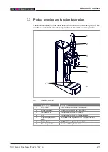
Page 21: ... entire working stroke 7 5 6 1 4 3 2 Fig 1 Product overview Designation Function 1 Hand lever Drives the ram onto the workpiece 2 Knurled screw Fine adjustment of working depth 3 Toothed rack Transfers the force to the ram 4 Ram Transfers the force to the workpiece 5 Height adjustment scale Facilitates the adjustment of the open height 6 Press bed With T groove for taking up tools 7 Fastening hole...

Page 22: ...About this product 22 TOX_Manual_FinePress_ZFS ZFL ZFW_en ...

Page 23: ...echnical data TOX_Manual_FinePress_ZFS ZFL ZFW_en 23 4 Technical data 4 1 Type sheet and data sheet For technical data and installation dimensions see type sheet and data https www tox pressotechnik com ...

Page 24: ...Technical data 24 TOX_Manual_FinePress_ZFS ZFL ZFW_en ...
Page 25: ...sporting and setting down make sure that no parts of the body become jammed è Wear suitable personal protective equipment e g safety boots CAUTION Injury from toppling and falling products è Secure product from toppling falling accidentally moving è Store product horizontally or secure with dowels The transportation may only be carried out by authorized personnel The product may only be transporte...

Page 26: ...roducts è Secure product from toppling falling accidentally moving è Store product horizontally or secure with dowels The following applies Do not store the product outdoors Protect the product against the influence of the weather Avoid temperature fluctuations so as to prevent corrosion from con densation Seal connection openings ...

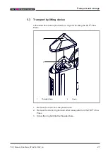
Page 27: ...ifting device A threaded bore hole is provided for a ring bolt for lifting the TOX Fine Press 2 1 1 Threaded hole 2 Cover 1 Remove the cover from the press frame 2 Remove the crank ring bolt and other loose parts from the TOX Fine Press 3 Screw the ring bolt into the threaded bore ...

Page 28: ...panying repair form This we supply in the service sector on our website or upon request via e mail Send us the completed form via e mail Then you will receive the shipping documents from us via e mail Send us the product with the shipping documents and a copy of the Accompanying repair form For contact data see Chap 1 7 Contact and source of supply Page 11or www tox pressotechnik com ...

Page 29: ...conducting lines Serious injuries to eyes and body cavities è Always connect and disconnect lines without pressure è Pay attention to maximum permitted pressures è Wear individual protective equipment WARNING Hazard from suspended loads Severe crushing impacts and serious accidents as a result of improper transportation and falling load è Only use lifting gear that is appropriate and in perfect te...

Page 30: ... ZFL ZFW_en 6 2 Requirements for installation 6 2 1 Set up location The set up location Must be free from dust and dirt Must be a closed room Must have a firm level floor The stability must be ensured The product must be screwed to the floor ...

Page 31: ...tion TOX_Manual_FinePress_ZFS ZFL ZFW_en 31 6 3 Installing accessories 6 3 1 Installing process monitoring option è Please see the separate operating manual for the installation of the process monitoring system ...

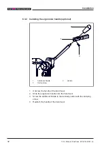
Page 32: ...onomic handle optional 2 1 3 1 Additional handle 2 Handle 3 Clamp screw 1 Unscrew the handle of the hand lever 2 Slide the ergonomic handle onto the hand lever 3 Screw the additional handle in the desired position with the clamping screw 4 Reattach the handle of the hand lever ...

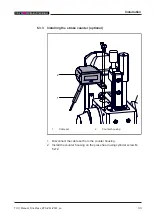
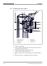
Page 33: ...Press_ZFS ZFL ZFW_en 33 6 3 3 Installing the stroke counter optional 2 1 1 Cable set 2 Counter housing 1 Disconnect the cable set from the counter housing 2 Install the counter housing on the press head using cylinder screw M 5x12 ...

Page 34: ...heet 2 Screw the push button with fixing device onto the press head cheese head screws M 3x8 3 Install the spring sheet 4 Check the switching point of the push button The push button must switch shortly before reaching the final position The switching point is set using the two nuts on the push button 5 Connect the cable set to the counter housing ...

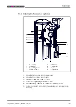
Page 35: ...fixing device 6 Clamp 7 Straight connector 8 Fixing device 1 Screw the fixing device onto the press head 2 Screw the force sensor onto the ram 3 Fasten the cable clamp with the screw 4 Connect the angled plug to the force sensor 5 Screw the clamp in the lowest position onto the fixing device 6 Connect the straight connector to the evaluation unit and insert it into the clamp ...

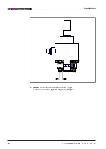
Page 36: ...Installation 36 TOX_Manual_FinePress_ZFS ZFL ZFW_en F2 F2 F1 F1 è NOTE Observe the maximum thread length The tool must bear against flange 1 or flange 2 ...

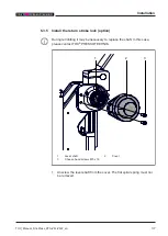
Page 37: ...eturn stroke lock option During retrofitting it may be necessary to replace the shaft In this case please contact TOX PRESSOTECHNIK 1 2 3 1 Lever shaft 2 Cover 3 Cheese head screws M5 x 16 1 Unscrew the lever shaft from the cover The flat spiral spring must nor be removed ...

Page 38: ... return stroke lock on the lever shaft and screw it on with the M 5x16 cylinder screws 3 The unlocking button must point to the front and be positioned on STOP 4 Insert the cam disc into the housing The cam disk must latch in on the lever shaft 5 Fix the lock washer with the M 6x12 locking screw 6 The return stroke lock must be adjusted See Adjusting the return stroke lock Page 50 7 Install the ho...

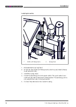
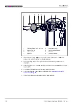
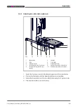
Page 39: ...g holes 7 Fastening groove T groove 8 Retract pneumatic connection 9 Pneumatic the cylinder op tional 10 Extend pneumatic connection 1 Insert the T groove nuts into the fastening groove of the press frame 2 Pull out the tool plate until the fastening holes are accessible 3 Screw the base plate over the mounting holes using the T groove nuts 4 The insertion width is set via the stop ...

Page 40: ...g 6 Fixing device 7 Counter nuts 1 Unscrew the product tag 2 Screw on the fixing device together with the tag The travel sensor is pointing towards the press frame 3 Screw the rear fixing device onto the press head 4 Connect the cable to the evaluation unit 5 Screw the straight connector to the fixing device using the fastening clip 6 Set the zero point see Setting the travel sensor Page 54 ...

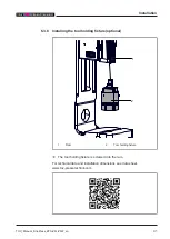
Page 41: ...S ZFL ZFW_en 41 6 3 8 Installing the tool holding fixture optional 2 1 1 Ram 2 Tool holding fixture è The tool holding fixture is screwed into the ram For technical data and installation dimensions see data sheet www tox pressotechnik com ...

Page 42: ...Installation 42 TOX_Manual_FinePress_ZFS ZFL ZFW_en ...

Page 43: ...s_ZFS ZFL ZFW_en 43 7 Commissioning 7 1 Safety during the commissioning The system may only be commissioned by trained and authorized service personnel 7 1 1 Safety device All safety equipment must be properly assembled and functional ...

Page 44: ... locks are removed Supply connections communication and control connections material or media hoses are installed properly The permissible values are com plied with The necessary software for controlling the component is installed TOX PRESSOTECHNIK has released the system and associated components for commissioning No tools installation equipment or other interfering objects may be left in the too...

Page 45: ... entire system are properly assembled and functional All piece parts are intact and properly maintained Supply connections communication and control connections material or media hoses are installed properly The permissible values are com plied with The main switches of the system or component are switched on The fault messages on the system or component are acknowledged 8 3 Process monitoring See...

Page 46: ...nual_FinePress_ZFS ZFL ZFW_en 8 4 Setting the open height of the press head 4 3 2 1 1 Fastening screws 2 Square 3 Crank 4 Cover NOTE Damage on the tool or the workpiece Calculate the open height be fore starting operation ...

Page 47: ...nscrew the screws 3 Place the supplied crank onto the square and adjust the open height by turning it Turning clockwise increases the open height Turning anti clockwise reduces the open height 4 Remove the crank and stow it away 5 Tighten the fastening screws of the clamping plate Observe the tight ening torques see Inspecting the fastening of the press head Page 61 6 NOTE Damage on the tool The t...

Page 48: ...g ring 3 Clamping nut 1 Loosen the clamping screw 2 Turn the adjusting ring to adjust the open height A line on the scale of the adjusting ring corresponds to a height adjust ment of 0 02 mm Turning clockwise increases the open height Turning anticlockwise reduces the open height 3 Fix the adjusting ring with the clamping screw ...

Page 49: ...rew corresponds to an adjustment of 1 mm Turn clockwise decrease working depth Turn anticlockwise increase working depth 1 The working depth can be set using the knurled screw 2 Secure the setting by tightening the counter nut 8 7 Resetting the stroke counter optional The stroke counter has a reset button è Press the stroke counter button ...

Page 50: ...Adjusting the return stroke lock optional NOTE Do not push the hand lever back while the mechanism is locked 1 2 6 3 5 4 1 Threaded hole position 1 2 Cheese head screw position 2 3 Cross bore hole 4 Unlocking device 5 Inner mechanism 6 Cheese head screws ...

Page 51: ... return stroke lock un locks The lock engages twice audibly with a click and unlocks by turn ing it further A suitable tool e g Allen key can be inserted into the cross bore hole to turn the mechanism 5 Tighten the cheese head screws positions 2 and 6 6 Install the housing cover Lever travel for position 1 4 0 2 4 2 4 1 7 3 2 1 4 1 Maximum lever opening OT 2 Return stroke activates return stroke l...

Page 52: ... Install the housing cover Lever travel for position 2 4 9 4 2 1 7 1 2 3 4 1 Return stroke activates return stroke lock 2 The return stroke lock engages during forward stroke 3 The return stroke lock engages during forward stroke 4 Forward stroke unlocks return stroke lock UT ü The return stroke lock has engaged ü The housing cover is removed 1 Unscrew the cheese head screw position 1 and screw it...

Page 53: ...ZFS ZFL ZFW_en 53 8 9 Setting the return stroke 2 1 1 Cheese head screw 2 Threaded bores 1 Press the hand lever down and hold 2 Remove the cheese head screw 3 Screw in the cheese head screw into the threaded bore at the new po sition ...

Page 54: ...he travel sensor option 1 1 Counter nuts of travel sensor 1 Loosen the counter nuts of travel sensor 2 Press the hand lever of the press firmly up and hold 3 Set the zero point on the travel sensor by turning the nut 4 Tighten the counter nuts of the travel sensor ...

Page 55: ...ZFS ZFL ZFW_en 55 9 Troubleshooting 9 1 Safety during troubleshooting Faults may only eliminated by trained and authorized service personnel The following applies Inform operating personnel before starting repair work Appoint a supervisor ...

Page 56: ...bed Fault Cause Measures The ram does not ex tend There is a mechanical fault on the guide Contact authorized service personnel The nominal force not reached There is a mechanical fault on the guide Contact authorized service personnel The press head is not adequately fastened Tighten the fastening screws evenly Observe the tightening torques see Inspecting the fas tening of the press head Page 61...

Page 57: ...n the area of application the actual values may differ from the guide values The ac tual intervals can be found in the system control Maintenance cycle Additional information Weekly 10 3 1 TOX FinePress inspecting Monthly 10 3 3 Inspecting and cleaning movable parts and guides Half yearly 10 3 2 Inspecting the fastening of the press head ...

Page 58: ...Maintenance table 58 TOX_Manual_FinePress_ZFS ZFL ZFW_en ...
Page 59: ...e maintenance intervals may have to be verified with the manufac turer if necessary Perform only maintenance work that is described in this manual Inform operating personnel before starting repair work Appoint a supervisor 10 2 Requirements for maintenance 10 2 1 Set system to maintenance position Unless specified otherwise before all maintenance work 1 Retract the working piston w Plant is in hom...

Page 60: ...nePress inspecting ü System is in maintenance position See Set system to maintenance position Page 59 1 Check the plant particularly moving parts for obvious defects and dam age 2 Check all parts inside and outside for wear obvious defects and dam age 3 Check the supply connections for tightness ...

Page 61: ... Fastening screws ü System is in maintenance position See Set system to maintenance position Page 59 1 Check the tightening torque of the fastening screws 2 NOTE Damage on the tool Check the alignment of the tool Screw size Tightening torque M 10 60 Nm Tab 2 Fastening screws of the press head on the frame ...

Page 62: ... Only touch bare areas with gloves è Use cleaning set such as industrial cleaner e g Loctite 7063 or Würth Montagekraftreiniger 0890 107 vacuum cleaner dry cloth and brush è Do not clean with compressed air but with suction è After cleaning protect bare outer surfaces from corrosion Coat sur faces with a cloth slightly moistened with anticorrosive fluid è Keep inside surfaces especially element ca...

Page 63: ...Repairs TOX_Manual_FinePress_ZFS ZFL ZFW_en 63 11 Repairs 11 1 Safety and repairs The system may only be repaired by trained and authorized service person nel ...

Page 64: ...Repairs 64 TOX_Manual_FinePress_ZFS ZFL ZFW_en ...
Page 65: ...es Serious injuries to eyes and body cavities è Always connect and disconnect lines without pressure è Pay attention to maximum permitted pressures è Wear individual protective equipment CAUTION Sharp edges caused by material splintering Injuries from worn parts è Wear individual protective equipment è Do not move fingers along the cutting edges è Be particularly careful and attentive 12 2 Decommi...

Page 66: ... Remove electrical supply line first at the terminal then on the ma chine 6 Remove compressed air supply line 7 Remove network connection 8 Clean the system and protect it against corrosion 9 Protect open cable ends against penetration of dirt 10 Do not remove cable identifications 12 4 Disassembling The system consists of recyclable materials NOTE Environmental damage Improper recycling endangers...

Page 67: ...X_Manual_FinePress_ZFS ZFL ZFW_en 67 12 5 Disposal When disposing of packaging consumables and spare parts including the machine and its accessories the relevant national environmental protection regulations must be complied with ...

Page 68: ...Disassembly and Disposal 68 TOX_Manual_FinePress_ZFS ZFL ZFW_en ...
Page 69: ...Appendices TOX_Manual_FinePress_ZFS ZFL ZFW_en 69 13 Appendices 13 1 Declaration of conformity ...

Page 70: ...Appendices 70 TOX_Manual_FinePress_ZFS ZFL ZFW_en ...

Page 71: ......

Page 72: ......

Page 73: ...28 Disposal 65 67 Safety 65 Document additional 8 Validity 8 Drive Fastening Inspecting 61 E Electromagnetic Hazard 16 Ergonomic handle Installing 32 Exclusion of liability 7 F Faults Detect 56 Fine adjustment Working stroke 48 FinePress Inspecting 60 Maintaining 60 Force sensor Installing 35 Function description 21 G Gender note 8 Guidelines 7 Guides Inspecting 62 H Hazard Contusion 16 Electrical...

Page 74: ...note 7 M Maintenance 59 FinePress 60 Requirement 59 Safety 59 Maintenance position 59 Measures Organizational 13 Misuse 20 Mounting Travel sensor 40 N Noise Hazard 17 Note Gender 8 General 10 Legal 7 Warning signs 9 O Open height of the press head Setting 46 operation 45 Process monitoring 45 Requirements 45 Safe 19 Safety 45 Organizational measures 13 P Process monitoring Installing 31 Process mo...

Page 75: ...Return stroke 53 Travel sensor 54 Working depth 49 Set up location 30 Shutdown 66 Slide table Installing 39 Source of supply 11 Storage 25 26 Stroke counter Installing 33 Resetting 49 Substances harmful to the wetting properties of lacquers LABS 20 T Target group 8 Technical data 23 Texts Highlighting 10 Tool holding fixture Installing 41 Transport 25 Attachment point 27 Safety 25 Travel sensor In...

Page 76: ...Index 76 TOX_Manual_FinePress_ZFS ZFL ZFW_en ...

Reviews: