9.
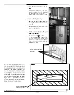
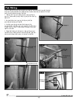
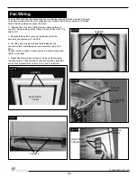
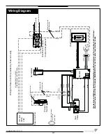
Route the communication cable as required to the wall control electrical box.
10. Attach the communication cable to the wall control. (Fig. #20)
11. Fasten the wall switch to the electrical box.
12.
Fasten the faceplate to switch
13. If not already installed, install the burner and media set using the instructions supplied
with the burner kit.
14. Turn on the gas supply and check that all connections are tight and leak free.
15. Turn on gas and electrical supplies.
17.
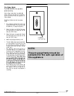
Press the up button on the wall control
and hold it for 5 seconds or until a clicking
sound is heard from the gas control (Fig.
#23). Release the button, check manifold
pressure and ensure that it’s correct.
(Refer to Burner installation manual)
18.
Press the center button of the wall control.
The fi replace will shut off.
19.
Install the remaining screws in the access
panel and tighten.
20. Remove the pressure gauge and the
extension test fi tting and thread the
pressure test port plug into the pressure
test port. Thread sealant is required on
the threads. (Refer to Burner installation
section in this manual)
21. Turn the fi replace on and verify that
the connections are tight.
16. Press the center button on the wall control (Fig. #22). The igniter will start to spark.
After a short time the pilot will light, followed by the main burner.
Fig. #20
Fig. #22
Fig. #23
16
TCWS.54CSTE 110712-72
Summary of Contents for TCWS54ST SERIES D
Page 70: ...70 TCWS 54CSTE 110712 72 ...


