background image

438B ALEXANDRA ROAD BLOCK B #06-01
ALEXANDRA TECHNOPARK
SINGAPORE 119968

TOSHIBA VIDEO PRODUCTS PTE LTD

W-603C  4/22/00 10:16 AM  Page 2

Summary of Contents for W603C

Page 1: ...icio Precauciones Información de referencia Especificaciones del producto Desemsamble y reensamble Ajuste y alineamiento Vista explotada Lista de partes de reemplazo Diagrama a bloques Diagramas PCB Placa de Circuito Impreso Diagramas esquemáticos ...

Page 2: ...SERVICE MANUAL FILE NO 120 200012 VIDEO CASSETTE RECORDER W 603C PRINTED IN KOREA APR 2000 W 603C 4 22 00 10 16 AM Page 1 ...

Page 3: ...ce Guide 1 Precautions 2 Reference Information 3 Product Specifications 4 Disassembly and Reassembly 5 Alignment and Adjustment 6 Exploded View 7 Replacement Parts List 8 Block Diagram 9 PCB Diagrams 10 Schematic Diagrams ...

Page 4: ...n replacing the Assy Cylinder be sure to replace only SEM Cylinder The only part no of SEM Cylinder is shown in the CH7 Replacement Parts List of Service Manual 3 When changing from ALPS connector pin 7 cylinder to SEM connector pin 5 cylinder Change CN605 Connector pin 7 pin 5 Change CN605B Cable Flat pin 7 pin 5 4 After replacing the SEM Cylinder use type C D G H optional for NVRAM Option Settin...

Page 5: ...pstan Motor use type E F G H optional for NVRAM Option Setting See page 5 9 Capstam Motor TM BLOCK 1 Two kinds of the TM Blovk Œ SIF available Not SIF available 2 How to identify TM Block See page 5 11 Fig 5 21 In case there is VR501 Not SIF available In case there is no VR501 SIF available 3 When replacing the TM Block as a service parts be sure to replace only the TM Block which is SIF available...

Page 6: ...eed 0 5 milliamp Reverse the power plug prongs in the AC outlet and repeat the test 6 X ray Limits The picture tube is designed to prohibit X ray emissions To ensure continued X ray protection replace the picture tube only with one that is the same type as the original Fig 1 1 AC Leakage Test 7 Antenna Cold Check With the unit s AC plug disconnected from the AC source connect an electrical jumper ...

Page 7: ...ument s ground lead to the instrument chassis ground before connecting the positive lead always remove the instrument s ground lead last 17 Observe the original lead dress especially near the following areas Antenna wiring sharp edges and especially the AC and high voltage power supplies Always inspect for pinched out of place or frayed wiring Do not change the spacing between components and the p...

Page 8: ...IN 1 AUDIO jacks L R RF OUT TO TV terminal LINE IN 1 VIDEO jack CH OUT TO TV IN FROM ANT LINE OUT LINE IN 1 VIDEO AUDIO 3 4 RF To wall outlet 8 CHANNEL PLAY STOP FF EJECT POWER REW 24 19 19 19 19 14 18 10 9 18 VIDEO L MONO AUDIO R LINE IN 2 REC 24 Front Panel Remote Control INTRODUCTION Identification of Controls See the page in for details This manual shows the names of buttons in italics CHANNEL...

Page 9: ... channel while recording it record an unscrambled channel while watching another only when you connect a cable compatible TV You will need to select TV channel 3 or 4 to receive video signals to record a channel while watching another press TV VCR on the remote control to turn off the VCR indicator in the VCR display and select a desired channel on the TV only when you connect a cable compatible T...

Page 10: ... another unscrambled channel only when you connect a cable compatible TV A B switch A record and watch an unscrambled channel which comes bypassing the cable box A B switch B record and watch a scrambled or unscrambled channel coming through the cable box Incoming cable Cable box OUT IN A B switch L R CH OUT TO TV IN FROM ANT LINE OUT LINE IN 1 VIDEO AUDIO 3 4 RF Cable box L R CH OUT TO TV IN FROM...

Page 11: ...or AUTO The VCR automatically sets or adjusts the clock If you select AUTO mode proceed to step 8 MANU You can set the clock manually If you select MANU mode proceed to next step 5 Vary the digits to set the hour CURSOR To increase CURSOR To decrease 6 Move to the next using CURSOR To move back press CURSOR 7 Repeat step 5 and 6 to set the minutes month day and the year by the last two digits Proc...

Page 12: ...els If a desired channel cannot be scanned automatically because of a weak signal it can be added to the memory Erasing channels You can erase a stored channel from the memory if it is unnecessary 1 Follow steps 1 to 3 of Incoming Antenna CATV Signals 2 Select ADD CH or ERASE CH using CURSOR or E n D PROG SET UP PRESET PROGRAM TV CATV TV CATV AUTO SCA n OFF O n ADD CH CH ERASE CH CH TO SET CH PUSH...

Page 13: ...or 4 or video input mode on the TV Press VCR to set the remote control operating the VCR S S L P VCR REC L TIMER REW CH TRK FF 3 2 1 Press PLAY during playback A tape runs at double speed playback Double Speed Playback 18 Video Cassette Use Loading a cassette Push the cassette into the cassette compartment with the window side facing up and the label side towards the front The VCR is automatically...

Page 14: ...n play back a tape at various tape speeds Picture Search A tape runs at 5 times or 7 times the normal playback speed so that you can quickly locate a particular scene 1 Press FF or REW during playback The tape runs at 5 times the normal playback speed 2 To change the tape speed to 7 times the normal playback speed press and hold FF or REW If you release it the tape speed returns to 5 times Note If...

Page 15: ...the MENU screen 3 Select SET UP using CURSOR or and press ENTER 4 Select the length of the tape using CURSOR or T120 for a T 120 tape or shorter T160 for a T 140 or T 160 tape T180 for a T 180 tape 5 Press PROG twice to exit 6 Press COUNTER The remaining time RT appears in the VCR display Notes The displayed remaining time is an approximation The remaining time is calculated according to the tape ...

Page 16: ...for 10 minutes Basic Recording 1 Load a cassette with the safety tab attached 2 Press TV VCR so that the VCR indicator appears in the VCR display 3 Select a channel to record with CHANNEL on the VCR or CH TRK or number buttons on the remote control If you see L1 or L2 in the VCR display press INPUT SELECT so that the channel number appears If you record cable channels via the cable box make the ou...

Page 17: ... VCR automatically selects the tape speed to record the program to the end If the tape length is not long enough the tape speed automatically changes from SP to SLP 5 Move to the next using CURSOR and set the recording date using CURSOR or The date changes as follows WKLYSU WKLYSA You can record TV programs on the same channel on the day and time every week MO FR You can record TV programs on the ...

Page 18: ...e or record MTS Multichannel TV Sound broadcasts By connecting the VCR to your stereo system or stereo TV you will experience the SAP or stereo sound Preparation Connect a stereo TV or stereo system to the AUDIO OUT jacks of the VCR Recording the SAP Stereo Broadcast 1 On the SET UP screen page 14 select SAP SET using CURSOR or and set to ON using CURSOR or 2 Press PROG twice to exit 3 Perform a r...

Page 19: ...04 11 Motorola 08 MTC 12 NAD 01 11 Nikko 11 Optimus 09 Optonica 08 Panasonic 07 10 15 Penney 01 02 07 11 12 Philco 10 Philips 10 Princeclub 12 Prism 07 Proscan 02 Proton 11 Table of Brand Codes Pulser 14 Quasar 07 15 Radio Shack 13 RCA 02 Realistic 09 11 13 Runco NEC 14 Samsung 11 12 Sanyo 09 Scotch 11 Scott 11 Sears 01 02 09 10 11 Sharp 08 13 Sony 03 Soundesign 11 Supreme 03 Sylvania 10 Tandy 08 ...

Page 20: ...Reference Information Toshiba 2 13 2 2 1 IC301 LA71072M 2 2 IC Blocks ...

Page 21: ...Reference Information 2 14 Toshiba 2 2 2 IC501 AN3662 ...

Page 22: ...Reference Information Toshiba 2 15 2 2 3 IC601 MN101D02X ...

Page 23: ...Reference Information 2 16 Toshiba MEMO ...

Page 24: ...onditions 120V AC 60Hz 18W 430 x 94 x 252 mm W H D 3 0 kg VHF Channels 2 13 UHF Channels 14 69 CATV Channels A7 A1 A CC 66 125 UHF VHF 75ohm F type connector Standard NTSC Recording VHS format SP SLP Playback VHS format SP LP SLP Video cassette with VHS mark SLP 11 1 mm s SP 33 4 mm s SLP 480 minutes SP 160 minutes When T 160 video cassette is used Within approx 120 s When T 120 video cassette is ...

Page 25: ...Product Specifications 3 2 Toshiba MEMO ...

Page 26: ...the Hook Fig 4 1 Cabinet Top Removal 4 1 2 Ass y Front Panel Removal Disconnect the CN701 from the Main PCB and then lift the Jack PCB up CN701 CN703 Disconnect the CN703 from the Main PCB and then lift the Key PCB up Fig 4 2 Ass y Front Panel Removal 4 1 3 Jack PCB Key PCB Removal Fig 4 3 Jack PCB Key PCB Removal Œ RELEASE 4 HOOKS RELEASE 2 HOOKS Top View Bottom View ...

Page 27: ...ˆ LIFT THE ASS Y FULL DECK UP Œ REMOVE 2 SCREWS REMOVE BRACKET FRAME ˇ REMOVE 2 SCREWS Ø LIFT THE ASS Y MAIN PCB UP TO REMOVE MODE SWITCH ASSEMBLY POINT When installing the ass y full deck on the Main PCB be sure to align the assembly point of mode switch Fig 4 4 Chassis Removal ...

Page 28: ...4 2 Deck Parts Locations 4 2 1 Top View Œ ˇ ˆ Ø Fig 4 5 Top parts Location 1 Œ BRACKET FL TOP Optional GEAR FL CAM ˇ MOTOR LOADING ASS Y LEVER FL ARM ASS Y ˆ HOLDER FL CASSETTE ASS Y Ø LEVER FL DOOR SLIDER FL DRIVE ...

Page 29: ... Location 2 Œ FE HEAD PLATE CYLINDER C ˇ CYLINDER ASS Y PLATE CYLINDER B ˆ PLATE CYLINDER A Ø ACE HEAD ASS Y UNIT PINCH ASS Y LEVER 9 GUIDE ASS Y LEVER TENSION ASS Y BAND BRAKE ASS Y Ô DISK S REEL LEVER S BRAKE ASS Y Ò GEAR IDLE Ú LEVER IDLE Æ LEVER T BRAKE ASS Y ı DISK T REEL ...

Page 30: ...4 2 2 Bottom View Œ ˇ ˆ Ø Ô Fig 4 7 Bottom Parts Location Œ GEAR JOINT 1 GEAR JOINT 2 ˇ BRAKET GEAR MOTOR CAPSTAN ASS Y ˆ LEVER T LOAD ASS Y Ø GEAR LOADING DRIVE LEVER S LOAD ASS Y HOLDER CLUTCH ASS Y BELT PULLEY SLIDER CAM Ô SLEEVE TENSION ...

Page 31: ...e Take care not to change assembly direction Œ 2 SCREWS BRACKET FL TOP 4 3 2 Lever FL Door Removal 1 Rotate the Lever FL Door Œ in the direction of arrow A 2 Release the Hook remove the Lever FL Door Œ in the direction of arrow B HOOK Œ LEVER FL DOOR A B 4 3 Main Deck Fig 4 8 Braket FL Top Removal Fig 4 9 Lever FL Door Removal ...

Page 32: ...ly Note Be sure to insert Lever FL Cassette R in the direction of A to prevent seperation and breakage of the Lever FL Cassette R at disassembling and reassembling Œ HOLDER FL CASSETTE ASS Y LEVER FL CASSETTE R BOSS A BOSS B RAIL C RAIL D A B 4 3 4 Lever FL Arm Ass y Removal 1 Remove the Lever FL Door Refer to Fig 4 9 2 Remove the Holder FL Cassette Ass y Refer to Fig 4 10 3 Release the Hook Œ in ...

Page 33: ...ction of arrow Refer ti Fig 4 12 Œ SLIDER FL DRIVE 4 3 6 Bracket Gear Gear FL Cam Gear Joint 1 2 Removal 1 Remove screw Œ 2 Lift the Bracket Gear 3 Remove the Gear FL Cam ˇ 4 Lift the Gear Joint 2 Gear Joint 1 ˆ Œ SCREW BRACKET GEAR ˇ GEAR FL CAM ˆ GEAR JOINT 1 GEAR JOINT 2 Fig 4 12 Slider FL Drive Removal Fig 4 13 Bracket Gear Gear FL Cam Gear Joint 1 2 Removal ...

Page 34: ...nt 3 Œ GEAR JOINT 1 GEAR JOINT 2 ˇ SLIDER CAM TIMING POINT 1 GEAR FL CAM GEAR WORM WHEEL POST TIMING POINT 2 TIMING POINT 3 4 3 8 Holder Worm Gear Worm Gear Worm Wheel Removal 1 Release the Hook A in the direction of arrow and remove the Holder Worm Œ 2 Remove the Gear Worm 3 Remove the Gear Worm Wheel ˇ After remov ing the Gear FL Cam as shown Fig 4 13 Note Secure the Hook A after installing the ...

Page 35: ... Ass y Removal 1 Remove the Belt Pulley Refer to Fig 4 33 2 Remove the Gear Loading Drive Œ after releasing Hook A in the direction arrow as shown in detail drawing 3 Remove the Slider Cam 4 Remove the Lever T S Load Ass y ˇ Œ GEAR LOADING DRIVE ˇ LEVER T LOAD ASS Y HOOK A SLIDER CAM LEVER S LOAD ASS Y Fig 4 16 Motor Loading Ass y Removal Fig 4 17 Gear Loading Drive Slider Cam Lever T S Load Ass y...

Page 36: ... TIMING POINT 2 TIMING POINT 3 4 3 12 Lever Tension Ass y Band Brake Ass y Sleeve Tension Removal 1 Remove the Spring Tension Œ 2 In bottom side of Deck remove the Sleeve Tension after rotating it right or left as liftinig locking edge of Sleeve Tension 3 Remove the side a of the Band Brake Ass y in the direction of arrow A from the Lever Tension Ass y ˇ 4 Remove the side b of the Band Brake Ass y...

Page 37: ... not to be folded and trans formed spring Brake at removing or reinstalling ˇ SPRING BRAKE LEVER T BRAKE ASS Y Œ LEVER S BRAKE ASS Y HOOK A HOOK C HOOK B 4 3 14 Lever Idle Ass y Removal 1 Push the Lever Idle Œ in the direction of arrow A B 2 Lift the Lever Idle Œ Assembly 1 Apply oil in two Bosses of Lever Idle Œ 2 Assemble the Gear Idle with the Lever Idle Œ Note When replacing the Gear Idle be s...

Page 38: ...tch Ass y 1 Check the condition of spring as shown in detail A 2 Don t push Holder Clutch Ass y down with exces sive force Just insert Holder Clutch Ass y into post center with dead force and rotate it smoothly Be sure to confirm that spring is in the slit of Gear Center Ass y as shown in detail B HOLDER CLUTCH ASS Y Œ WASHER SLIT BAD GOOD BAD GOOD SPRING SPRING DETAIL A DETAIL B Fig 4 22 Disk S T...

Page 39: ...2 Lift the Lever Up Down Ass y Œ about 35 degree Refer to Fig 4 25 3 Insert Ring of the Gear Center Ass y in the Guide ˆ of the Lever Up Down Ass y Œ 4 Insert the Gear Center Ass y in the post Ø on Main Base 5 Push down the Lever Up Down Ass y Œ for lock ing of the Hook Note 1 Take care not to separate and loose the Spring Up Down 2 When assembling the Gear Center Ass y don t push down too much MA...

Page 40: ...Unit Pinch Ass y Plate Joint Spring Pinch Drive Removal 1 Lift the Unit Pinch Ass y Œ 2 Remove the Plate Joint from Lever Pinch Drive 3 Remove the Spring Pinch Drive ˇ Note 1 Take extreme care not to touch the grease on the Roller Pinch 2 When reinstalling be sure to apply grease on the post pinch roller Œ UNIT PINCH ASS Y PLATE JOINT ˇ SPRING PINCH DRIVE Fig 4 26 Guide Cassette Door Removal Fig 4...

Page 41: ... arrow Note 1 Take extreme care not to touch the grease on the tape Guide Post 2 After reinstalling check the bottom side of the Post 9 Guide to stick to the top side of Main Base LEVER 9 GUIDE ASS Y Œ SPRING 9 GUIDE 4 3 22 FE Head Removal 1 Remove the screw Œ 2 Lift the FE Head Œ SCREW FE HEAD Fig 4 28 Lever 9 Guide Ass y Removal Fig 4 29 FE Head Removal ...

Page 42: ...tor of ACE Head Ass y 2 Remove the screw Œ 3 Lift the ACE Head Ass y Œ SCREW ACE HEAD ASS Y 4 3 24 Slider S T Ass y Removal 1 Move the Slider S T Ass y Œ to slot and then lift it to remove Refer to arrow SLIDER T ASS Y Œ SLIDER S ASS Y Fig 4 30 ACE Head Removal Fig 4 31 Slider S T Ass y Removal ...

Page 43: ...care not to touch the Cylinder Ass y and the tape guide post at reinstalling Plate Cylinder C 3 Take care not to touch the Cylinder Ass y with screw driver at reinstalling the Plate Cylinder C ˆ SCREW CYLINDER ASS Y Œ SCREW PLATE CYLINDER C ˇ SCREW PLATE CYLINDER B Ø PLATE CYLINDER A 4 3 26 Belt Pulley Removal 1 Remove the Belt Pulley Œ Note Take extreme care not to touch the grease on Belt Pulley...

Page 44: ... How to Eject the Cassette Tape If the unit does not oprate on condition that is inserted into housing ass y 1 Remove the Holder worm Œ and the Gear Worm 2 Turn the Gear Worm Wheel ˇ counterclockwise with screw driver Refer to arrow Œ HOLDER WORM GEAR WORM SCREW DRIVER ˇ GEAR WORM WHEEL Fig 4 34 Motor Capstan Ass y Removal Fig 4 35 3 When Slider S T are approched in the position of unloading rotat...

Page 45: ...IDE SHAFT CAPSTAN SHAFT 9 GUIDE POST 3 GUIDE POST GUIDE ROLLER S T O O O O O O O CYLINDER ASS Y O O O O O O O O O FE HEAD O O O O O O O ACE HEAD O O O O O O O O O PINCH ROLLER O O O O O O O O O POST REEL S T SLEEVE TENSION POST CENTER LEVER IDLE BOSS 2Point CAPSTAN MOTOR PULLEY O O O O O BELT PULLEY O O O O O O O HOLDER CLUTCH ASS Y O O O O O O O O O GEAR CENTER ASS Y O O O O O O O O O GEAR IDLE 2...

Page 46: ...he X Point and Head switching adjustment 4 Remote control used for same chassis as a accessory is available for all adjustments 5 How to adjustment Intermittently short circuit the test point on Main PCB with pincets to set the adjustment mode If the corresponding adjustment button is pressed the adjustment is preformed automatically If the adjustment is completed be sure to turn the power off 5 1...

Page 47: ...5 2 Toshiba Alignment and Adjustment 5 1 2 Test point location for adjustment mode setting Fig 5 2 Main PCB Top View Short Circuit ...

Page 48: ...for the transport adjustment To maintain the height of the tape guide and prevent damage do not apply excessive force onto the main base Fig 5 3 Location of Tape Transport Adjustment Fig 5 4 Tape Travel Diagram CYLINDER ASS Y TAKE UP REEL DISK 8 GUIDE POST 9 GUIDE POST SUPPLY REEL DISK CAPSTAN PINCH ROLLER GUIDE ROLLER T GUIDE ROLLER S FULL ERASE HEAD 3 GUIDE POST TENSION POST HEIGHT SCREW TILT SC...

Page 49: ...oes not occur at the tape guides 1 If tape wrinkle is observed at the guide roller S T turn the guide roller S T until wrinkle disappears 2 If the tape wrinkle is still observed at the tape guide perform the tilt adjustment of the ACE head 1 ACE Head Assembly Adjustment Test point TP601 Control Pulse TP602 H D S W Trigger TP301 Envelope TP302 Audio output TP303 Video output Test tape ST N1 BLANK T...

Page 50: ...lower flange of tape guide as shown in Fig 5 8 B 3 If a curl or wrinkle of the tape occurrs slightly turn the screw A tilt adjust on the ACE head ass y 4 Reconfirm the ACE head height Fig 5 8 Tape Guide Check c AUDIO AZIMUTH ADJUSTMENT 1 Load alignment tape Mono scope and playback the 7KHz signal 2 Connect channel 1 scope probe to audio output test point TP302 3 Adjust screw B to achieve maximum a...

Page 51: ... envelope at the exit side 4 If the section A in Fig 5 10 does not meet the spec ification adjust the guide roller S up or down 5 If the section B in Fig 5 10 does not meet the speci fication adjust the guide roller T up or down Fig 5 09 Envelope Waveform Adjustment a a b c d c b d a 63 b c d Fig 5 10 Adjustment Points A B A B H D SWITCHING PULSE ENVELOPE 6 Play back the Mono Scope alignment tape ...

Page 52: ...12 Video Envelope Rising when Operation mode Changes from RPS to Play Mode 4 Envelope Check 1 Make recordings on T 120 E 120 and T 160 E 180 tape Make sure the playback output envelope meets the specification as shown in Fig 5 13 2 Play back a self recorded tape recording made on the unit using with T 120 E 120 The video envelope should meet the specification as shown in Fig 5 13 In SP mode A shou...

Page 53: ...dge of Lever Tension Ass y and the quanity of crossing from mark on Main Base 1 0 0 5mm Counterclockwise Torque UP Clockwise Torque DOWN Back Tension should be 56 15g cm at inspecting it with Back Tension Meter 1 0mm 0 5mm ˇ LEVER TENSION ASS Y Œ DISK S REEL ADJUSTING ADJUSTING SLIT 1 3 Fig 5 16 Tension Pole and Back Tension Adjustment 5 2 4 Location adjustment and Confirmation of Tension Post 1 R...

Page 54: ...e PLAY button of remote control If PLAY button is pressed the selected number is changes reversed color See Fig 5 17 5 Press the ENTER button of remote control again to store the option number SAVE is displayed for a second as shown Fig 5 18 this setting is completed 6 Turn the Power off 1 NVRAM Option is adjusted at production line basically 2 In case Micom IC601 and NVRAM IC603 EEPROM is replace...

Page 55: ...ment How to identify the Assy Cylinder Fig 5 19 ALPS Cylinder SEM Cylinder CONNECTOR Pin 7 or Pin 5 CONNECTOR Pin 5 TOP VIEW SANKYO CAPSTAN MOTOR SEM CAPSTAN MOTOR CAPSTAN SHAFT CAPSTAN SHAFT Fig 5 20 How to identify the Capstan Motor ...

Page 56: ...Alignment and Adjustment Toshiba 5 11 Fig 5 21 Main PCB Top View VR501 Location for VR501 ...

Page 57: ...5 12 Toshiba Alignment and Adjustment MEMO ...

Page 58: ...Toshiba 6 1 6 Exploded View 6 1 Packing Assembly 6 2 Instrument Assembly 6 3 Mechanical Parts Top Side 6 4 Mechanical Parts Bottom Side 6 2 6 3 6 4 6 5 ...

Page 59: ...Exploded View 6 2 Toshiba 6 1 Packing Assembly A702 A701 A702 Y101 Y102 UT01 ...

Page 60: ...View Toshiba 6 3 6 2 Instrument Assembly 153 FULL DECK S N A BRACKET FRAME S N A 157 701 702 157 101 155 TM401B 601 S601A LD601A S602A 200 CN605B CN303B BOTTOM COVER S N A S N A Service Not Available 21 22 1 31 ...

Page 61: ...K250 K248 K110 K502 K350 K330 K182 K140 K490 K530 K240 G532 G450 K546 G510 B410 B440 B444 B446 B448 B452 G527 G520 G480 G680 OPTIONAL S N A S N A K470 B474 S N A G530 K180 K340 B473 K188 G555 G546 S N A Service Not Available K544 K542 B239 G428 G420 G458 OPTIONAL ...

Page 62: ...Exploded View Toshiba 6 5 6 4 Mechanical Parts Bottom Side G542 B560 B484 B257 B458 B500 B488 B257 B478 B462 B460 OPTIONAL B456 B468 B464 B258 K222 K200 K225 K221 B570 B238 S N A Service Not Available ...

Page 63: ...Exploded View 6 6 Toshiba MEMO ...

Page 64: ...730447 AC61 11045A BRACKET GEAR SECC20 20 T1 2 X 9 B462 BY730073 AC60 10517A SCREW TAP TITE PH M2 6 L5 ZPC YE B464 BY730381 AC66 80140A SLIDER CAM SECC20 20 T1 2 X 9 B468 BY730450 AC66 30541A LEVER PINCH DR ASSY X 9 B473 BY730090 AC61 60559A SPRING PINCH DRIVE TS SUS304 PI0 5 OD4 B474 BY730244 AC61 30180A PLATE JOINT SECC20 20 T0 8 X 9 B478 BY730449 AC66 30540A LEVER TENS DR ASSY X 9 B484 BY730110...

Page 65: ... 000442 TR SMALL SIGNAL KTC3203 Y NPN 400MW T0 9 Q306 70795134 0501 000303 TR SMALL SIGNAL KSA733 PNP 250mW TO 92 T Q307 70795142 0501 000442 TR SMALL SIGNAL KTC3203 Y NPN 400MW T0 9 Q308 70795142 0501 000442 TR SMALL SIGNAL KTC3203 Y NPN 400MW T0 9 Q311 70795136 0501 000398 TR SMALL SIGNAL KSC945 NPN 250mW TO 92 T Q501 70795142 0501 000442 TR SMALL SIGNAL KTC3203 Y NPN 400MW T0 9 Q701 70795134 05...

Page 66: ...00 L302 BY330019 3301 000297 CORE FERRITE BEAD AA 3 6x1 2x5 7mm 1400 L303 BY330019 3301 000297 CORE FERRITE BEAD AA 3 6x1 2x5 7mm 1400 L304 BY330019 3301 000297 CORE FERRITE BEAD AA 3 6x1 2x5 7mm 1400 L305 BY330019 3301 000297 CORE FERRITE BEAD AA 3 6x1 2x5 7mm 1400 L306 70795171 2702 000120 INDUCTOR RADIAL 15mH 5 6 2x7 4mm L307 70795168 2702 000108 INDUCTOR RADIAL 100uH 5 6x6 4mm L501 70795168 27...

Page 67: ... 001689 C CERAMIC CHIP MELF 8 2NF 30 16V Y5S BK C345 BY130041 2301 001014 C FILM PEF 6 8nF 5 50V TP 7x3x6 5mm C346 70796281 2203 000260 C CERAMIC CHIP 10nF 10 50V X7R TP 2012 C349 70795254 2203 001671 C CERAMIC CHIP MELF 56PF 5 50V Y5E TP 2 C350 BY130049 2401 002144 C AL 47uF 20 16V GP TP 5x11 5 C351 70795075 2202 000797 C CERAMIC MLC AXIAL 10NF 30 16V Y5S TP C352 BY130145 2301 000253 C FILM PEF 3...

Page 68: ... 12nF 10 50V X7R TP 2012 C610 BY130020 2203 000989 C CERAMIC CHIP 47nF 10 50V X7R TP 2012 C611 BY130350 2202 000253 C CERAMIC MLC AXIAL 4 7nF 20 16V Y5R TP C612 70795240 2203 001577 C CERAMIC CHIP MELF 150PF 10 50V Y5E TP C613 BY130039 2203 005549 C CERAMIC CHIP MELF 10nF 80 20 16V Y5V C614 BY130280 2401 002165 C AL 100uF 20 16V GP TP 6 3x7 5 C615 70795075 2202 000797 C CERAMIC MLC AXIAL 10NF 30 1...

Page 69: ...CHIP MELF 8 2KOHM 5 1 8W DB BK 2012 R311 70795221 2007 001513 R CHIP MELF 4 7KOHM 5 1 8W DB BK 2012 R313 70795020 2001 000449 R CARBON 2 2KOHM 5 1 8W AA TP 1 8X3 2M R314 BY230028 2007 001456 R CHIP MELF 820KOHM 5 1 8W DB BK 2012 R315 70796179 2007 001633 R CHIP MELF 1 5Kohm 5 1 8W DB BK 2012 R316 70795213 2007 001629 R CHIP MELF 1 8Kohm 5 1 8W DB BK 2012 R317 70796179 2007 001633 R CHIP MELF 1 5Ko...

Page 70: ...0KOHM 5 1 8W DB BK 2012 R608 70795005 2001 000429 R CARBON 1KOHM 5 1 8W AA TP 1 8X3 2MM R609 70795005 2001 000429 R CARBON 1KOHM 5 1 8W AA TP 1 8X3 2MM R610 70795005 2001 000429 R CARBON 1KOHM 5 1 8W AA TP 1 8X3 2MM R611 70796182 2007 001627 R CHIP MELF 100Kohm 5 1 8W DB BK 2012 R613 70795040 2001 000734 R CARBON 4 7KOHM 5 1 8W AA TP 1 8X3 2M R614 70795005 2001 000429 R CARBON 1KOHM 5 1 8W AA TP 1...

Page 71: ...5007 2001 000273 R CARBON 100KOHM 5 1 8W AA TP 1 8X3 2M R7FT10 70795007 2001 000273 R CARBON 100KOHM 5 1 8W AA TP 1 8X3 2M R7FT11 70795007 2001 000273 R CARBON 100KOHM 5 1 8W AA TP 1 8X3 2M R7FT12 70795007 2001 000273 R CARBON 100KOHM 5 1 8W AA TP 1 8X3 2M R7FT13 70795007 2001 000273 R CARBON 100KOHM 5 1 8W AA TP 1 8X3 2M R7FT14 70795007 2001 000273 R CARBON 100KOHM 5 1 8W AA TP 1 8X3 2M R7FT15 70...

Page 72: ...32001 3404 000165 SWITCH TACT 12V 50mA 160gf 6x6mm SPST SW7W07 BY632001 3404 000165 SWITCH TACT 12V 50mA 160gf 6x6mm SPST SW7W08 BY632001 3404 000165 SWITCH TACT 12V 50mA 160gf 6x6mm SPST SW7W09 BY632001 3404 000165 SWITCH TACT 12V 50mA 160gf 6x6mm SPST SWTW05 BY632001 3404 000165 SWITCH TACT 12V 50mA 160gf 6x6mm SPST TM401 BY634275 AC40 00007A TM BLOCK 115VD025AP NTSC M 115VD025AP Y VA1SS1 BY6340...

Page 73: ...Replacement Parts List 7 10 Toshiba MEMO ...

Page 74: ...Toshiba 8 1 8 Block Diagram ...

Page 75: ...Block Diagram 8 2 Toshiba MEMO ...

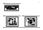
Page 76: ...Toshiba 9 1 9 PCB Diagrams 9 2 9 3 9 3 9 3 9 1 Main 9 2 VFD 9 3 Jack 9 4 Key ...

Page 77: ...PCB Diagrams 9 2 Toshiba 9 1 Main ...

Page 78: ...PCB Diagrams Toshiba 9 3 9 2 VFD 9 3 Jack 9 4 Key ...

Page 79: ...PCB Diagrams 9 4 Toshiba MEMO ...

Page 80: ...0 1 10 Schematic Diagrams 10 2 10 3 10 4 10 6 10 8 10 10 10 11 10 12 Block Identification of Main PCB 10 1 S M P S Power 10 2 Logic 10 3 A V 10 4 Hi Fi MTS 10 5 TM Block Input Output 10 6 VFD 10 7 Remote Control ...

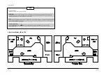
Page 81: ...electrostatically sensitive ES devices section of this service manual Note Do not use the part number shown on this drawing for ordering The correct part number is shown in the parts list may be slightly different or amended since this drawing was prepared Important safety notices Components identified with the mark have the special characteristics for safety When replacing any of these components...

Page 82: ...Schematic Diagrams Toshiba 10 3 10 1 S M P S Power ...

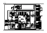
Page 83: ...Schematic Diagrams 10 4 Toshiba IC601 VFD 10 2 Logic ...

Page 84: ...8 33 5 5 5p p 58 5 5 5 83 0 0 0 9 34 0 5p p 5p p 59 5 5 5 84 0 0 0 10 35 0 0 5p p 60 0 0 0 85 0 0 0 11 36 5 5 5 61 0 0 0 86 0 0 0 12 37 Clock data 62 0 0 0 87 5 5 5 13 0 0 0 38 63 0 5 5 88 5 5 5 14 39 0 0 0 64 0 0 0 89 15 5 VCR 5 TV 0 40 Clock data 65 0 5p p 5p p 90 16 Safety Tab YES 5 NO 0 41 66 0 5p p 5p p 91 17 42 5 5 5 67 0 5 5p p 92 18 43 0 0 5p p 68 0 0 0 93 5p p data for LED display 19 0 0 ...

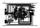
Page 85: ...Schematic Diagrams 10 6 Toshiba 10 3 A V ...

Page 86: ...8 Video Out Video Out 60 0 9 3 8 3 8 85 0 0 7 0 7 11 2 2 3 1 0 36 0 1 1 61 0 5 4 4 86 0 0 0 12 5 5 0 37 1 3 1 3 1 3 62 0 2 7 2 7 87 0 5 5 13 0 0 8p p 0 8p p 38 Video from L1 rear 63 0 2 2 88 0 4 4 1 8 14 0 0 8p p 0 8p p 39 0 3 5 3 5 64 0 7 2 2 2 2 89 0 4 4 1 8 15 0 0 8 0 40 Video from L2 front 65 0 4 4 90 0 4 4 1 8 16 5 5 0 3 41 0 0 2 5 66 0 2 0 91 0 4 4 1 8 17 2 2 2 2 0 42 Video from TM block 67 ...

Page 87: ...Schematic Diagrams 10 8 Toshiba 10 4 Hi Fi MTS ...

Page 88: ... 0 0 0 54 0 3 2 5 2 5 7 0 7 2 2 2 2 23 0 0 0 39 0 0 0 55 0 0 0 8 0 6 0 7 0 7 24 0 2 5 0 6 40 1 5 5 56 0 2p p 2 2p p 9 Audio R from rear jack L1 25 0 5 5 41 0 0 0 57 0 4 6 4 6 10 26 0 2 5 0 42 5p p for Hi Fi data clock 58 0 3 9 9 11 0 0 0 27 5 5p p 5p p 43 59 Audio to TM block 12 0 7 2 2 28 0 4 4 4 4 44 0 4 2 4 2 4 60 0 0 0 13 0 3 2 3 2 3 29 0 7 1 9 1 9 45 0 0 0 61 0 2 5 2 5 14 Audio R from rear ja...

Page 89: ...Schematic Diagrams 10 10 Toshiba 10 5 TM Block Input Ouput ...

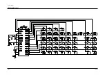
Page 90: ...Schematic Diagrams Toshiba 10 11 10 6 VFD ...

Page 91: ...Schematic Diagrams 10 12 Toshiba 10 7 Remote Control ...

Page 92: ...438B ALEXANDRA ROAD BLOCK B 06 01 ALEXANDRA TECHNOPARK SINGAPORE 119968 TOSHIBA VIDEO PRODUCTS PTE LTD W 603C 4 22 00 10 16 AM Page 2 ...

Reviews: