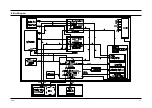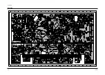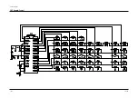
Schematic Diagrams
Toshiba
10-5
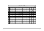
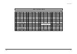
* These values are measured with a Hi-Fi standard tape.
* 5p-p means 5 volts peak to peak. It’s a kind of data or clock wave form.
* The value under 0.5 volt is regarded as 0 volt.
Unit : Volt
Pin No. Power Off
Stop(EE)
Play
Pin No.
Power Off
Stop(EE)
Play
Pin No. Power Off
Stop(EE)
Play
Pin No. Power Off
Stop(EE)
Play
1
0
5 or 0
5p-p
26
5
5
5p-p
51
5
5
5
76
2.5
2.5 0
2
0
5 or 0
5p-p
27
0
0
0
52
2.8
2.8
2.8
77
0
2.5 0
3
0
0
0
28
0
0
0
53
2.5
2.5
2.5
78
0
0
0
4
0
0
0
29
PB:1.3, EE:2.2, REC:5
54
0
0
0
79
0
5
2.5
5
30
SP:0, LP:0, SLP:0
55
0
0
0
80
0
0
3
6
31
0
0
0
56
0
0
0
81
0
2.2p-p
2.2p-p
7
32
2
5
0
57
5
5
5
82
5
5
5
8
33
5
5
5p-p
58
5
5
5
83
0
0
0
9
34
0
5p-p
5p-p
59
5
5
5
84
0
0
0
10
35
0
0
5p-p
60
0
0
0
85
0
0
0
11
36
5
5
5
61
0
0
0
86
0
0
0
12
37
Clock data
62
0
0
0
87
5
5
5
13
0
0
0
38
63
0
5
5
88
5
5
5
14
39
0
0
0
64
0
0
0
89
15
5 VCR:5, TV:0
40
Clock data
65
0
5p-p
5p-p
90
16
Safety Tab, YES:5, NO:0
41
66
0
5p-p
5p-p
91
17
42
5
5
5
67
0
5
5p-p
92
18
43
0
0
5p-p
68
0
0
0
93
5p-p data for LED display
19
0
0
0
44
0
0
5p-p
69
2.5
2.5
2.5
94
20
0
0
0
45
5
5
0
70
2.5
2.5
2.5
95
21
0
0
0
46
5
5
0
71
0
0
0
96
22
0
0
0
47
Video out signal
72
2.5
2.5
2.5
97
23
0
5p-p
5p-p
48
0
0
0
73
5
5
5
98
0
5p-p
5p-p
24
0
0
0
49
Video input signal
74
2.5
2.5
2.5
99
0
5
0
25
5
5
5
50
75
2.5
2.5
2.5
100
0
1
0
IC601 VOLTAGE TABLE
None input : 5, Any input : 5p-p
5p-p data for LED display
5V when the front video jack is inerted
5p-p for Hi-Fi/EEPROM/PLL data,clock
Summary of Contents for W603C
Page 20: ...Reference Information Toshiba 2 13 2 2 1 IC301 LA71072M 2 2 IC Blocks ...
Page 21: ...Reference Information 2 14 Toshiba 2 2 2 IC501 AN3662 ...
Page 22: ...Reference Information Toshiba 2 15 2 2 3 IC601 MN101D02X ...
Page 23: ...Reference Information 2 16 Toshiba MEMO ...
Page 25: ...Product Specifications 3 2 Toshiba MEMO ...
Page 56: ...Alignment and Adjustment Toshiba 5 11 Fig 5 21 Main PCB Top View VR501 Location for VR501 ...
Page 57: ...5 12 Toshiba Alignment and Adjustment MEMO ...
Page 59: ...Exploded View 6 2 Toshiba 6 1 Packing Assembly A702 A701 A702 Y101 Y102 UT01 ...
Page 63: ...Exploded View 6 6 Toshiba MEMO ...
Page 73: ...Replacement Parts List 7 10 Toshiba MEMO ...
Page 74: ...Toshiba 8 1 8 Block Diagram ...
Page 75: ...Block Diagram 8 2 Toshiba MEMO ...
Page 76: ...Toshiba 9 1 9 PCB Diagrams 9 2 9 3 9 3 9 3 9 1 Main 9 2 VFD 9 3 Jack 9 4 Key ...
Page 77: ...PCB Diagrams 9 2 Toshiba 9 1 Main ...
Page 78: ...PCB Diagrams Toshiba 9 3 9 2 VFD 9 3 Jack 9 4 Key ...
Page 79: ...PCB Diagrams 9 4 Toshiba MEMO ...
Page 82: ...Schematic Diagrams Toshiba 10 3 10 1 S M P S Power ...
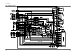
Page 83: ...Schematic Diagrams 10 4 Toshiba IC601 VFD 10 2 Logic ...
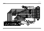
Page 85: ...Schematic Diagrams 10 6 Toshiba 10 3 A V ...
Page 87: ...Schematic Diagrams 10 8 Toshiba 10 4 Hi Fi MTS ...
Page 89: ...Schematic Diagrams 10 10 Toshiba 10 5 TM Block Input Ouput ...
Page 90: ...Schematic Diagrams Toshiba 10 11 10 6 VFD ...
Page 91: ...Schematic Diagrams 10 12 Toshiba 10 7 Remote Control ...


