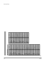
Reference Information
2-8
Toshiba
23
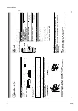
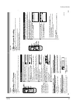
PLAYBACK
1
On the SET UP screen, select
“COUNTER MEM.
” using
CURSOR
(
▲
)
or
(
▼
), and set to
“ON
” using
CURSOR ( )
or
( )
.
2
Press
PROG.
twice to exit.
The memory-stop feature allows you to quickly return to a
counter reading of
“0H00M00S
” from any point on the tape.
Memory stop is automatically turned on whenever the time
counter with memory is displayed on the
TV screen.
This is
convenient when you want to watch a segment of the tape
repeatedly
.
Y
ou may also discover other useful application for
this feature.
Notes:
If you are rewinding the tape and the VCR stops at
“0H00M00S M
”, press
REW
again to continue
rewinding.
If you press the
FF
(fast-forward) button and the time
counter never reaches
“0H00M00S M
” between that
point and the end of the tape, the VCR will continue to
fastforward to the end of the tape.
Memor
y Stop Featur
e (Zer
o Return)
▼
▼
COUNTER
CURSOR
C.RESET DISPLA
Y
ENTER
PR
OG
E
n
D : PROG
SET UP
PRESET
PROGRAM
TAPE LE
n
GTH
120 160 180
COU
n
TER MEM
on off
LA
n
GUAGE E
n
G FRA ESP
SAP SET
on off
22
PLA
YBACK
Useful Functions in T
ape Opera
tion
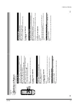
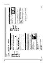
These functions will help your playback.
Tape Remaining Time
T
o
view the tape remaining time in the VCR display
, select the
tape length beforehand.
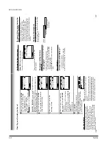
1
T
urn on the VCR and load a cassette.
2
Press
PROG.
to display the MENU screen.
3
Select
“SET UP
” using
CURSOR ( )
or
( )
, and press
ENTER
.
4
Select the length of the tape, using
CURSOR ( )
or
( )
.
T120:
for a
T
-120 tape or shorter
T160:
for a
T
-140 or
T
-160 tape
T180:
for a
T
-180 tape
5
Press
PROG
. twice to exit.
6
Press
COUNTER
.
The remaining time (
“R
T
- : - -
”) appears in the VCR display
.
Notes
•
The displayed remaining time is an approximation.
•
The remaining time is calculated according to the tape speed (SP or SLP)
and the cassette type.
Counter Function
Y
ou can view the clock, linear time counter or tape remaining
time in the VCR display or on the
TV screen.
Each time you press
COUNTER
, the VCR display changes in
sequence as follows:
The indication above will also appear on the
TV screen by pressing
DISPLA
Y
.
They are switchable with
COUNTER
.
To reset the linear time counter to “0:00:00”
The counter is automatically reset to
“0:00:00
” when a cassette is
ejected. If you want to reset at another point, such as the beginning of a
new recording, just press
C. RESET
.
Notes
•
The linear time counter does not work on non-recorded portions on the tape.
•
When the tape is ejected or the VCR is turned off, the display changes to
clock.
•
If the tape rewinds back over
“0:00:00
”,
“–”
appears in the VCR display.
•
The displayed time of the linear time counter is only an approximation.
→
Linear time counter
→
Tape remaining time (RT)
→
Clock
▼
▼
▼
▼
COUNTER
C.RESET DISPLA
Y
ENTER
PR
OG
CURSOR
E
n
D : PROG
SET UP
PRESET
PROGRAM
TAPE LE
n
GTH
120 160 180
SAP SET
on off
COU
n
TER MEM
on off
LA
n
GUAGE E
n
G FRA ESP
Summary of Contents for W603C
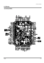
Page 20: ...Reference Information Toshiba 2 13 2 2 1 IC301 LA71072M 2 2 IC Blocks ...
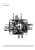
Page 21: ...Reference Information 2 14 Toshiba 2 2 2 IC501 AN3662 ...
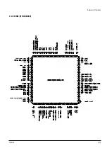
Page 22: ...Reference Information Toshiba 2 15 2 2 3 IC601 MN101D02X ...
Page 23: ...Reference Information 2 16 Toshiba MEMO ...
Page 25: ...Product Specifications 3 2 Toshiba MEMO ...
Page 56: ...Alignment and Adjustment Toshiba 5 11 Fig 5 21 Main PCB Top View VR501 Location for VR501 ...
Page 57: ...5 12 Toshiba Alignment and Adjustment MEMO ...
Page 59: ...Exploded View 6 2 Toshiba 6 1 Packing Assembly A702 A701 A702 Y101 Y102 UT01 ...
Page 63: ...Exploded View 6 6 Toshiba MEMO ...
Page 73: ...Replacement Parts List 7 10 Toshiba MEMO ...
Page 74: ...Toshiba 8 1 8 Block Diagram ...
Page 75: ...Block Diagram 8 2 Toshiba MEMO ...
Page 76: ...Toshiba 9 1 9 PCB Diagrams 9 2 9 3 9 3 9 3 9 1 Main 9 2 VFD 9 3 Jack 9 4 Key ...
Page 77: ...PCB Diagrams 9 2 Toshiba 9 1 Main ...
Page 78: ...PCB Diagrams Toshiba 9 3 9 2 VFD 9 3 Jack 9 4 Key ...
Page 79: ...PCB Diagrams 9 4 Toshiba MEMO ...
Page 82: ...Schematic Diagrams Toshiba 10 3 10 1 S M P S Power ...
Page 83: ...Schematic Diagrams 10 4 Toshiba IC601 VFD 10 2 Logic ...
Page 85: ...Schematic Diagrams 10 6 Toshiba 10 3 A V ...
Page 87: ...Schematic Diagrams 10 8 Toshiba 10 4 Hi Fi MTS ...
Page 89: ...Schematic Diagrams 10 10 Toshiba 10 5 TM Block Input Ouput ...
Page 90: ...Schematic Diagrams Toshiba 10 11 10 6 VFD ...
Page 91: ...Schematic Diagrams 10 12 Toshiba 10 7 Remote Control ...


