5-8
Toshiba
Alignment and Adjustment
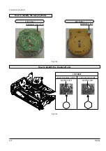
5-2-3 Reel Torque
1) The rotation of the capstan motor causes the
holder clutch ass’y to rotat through the belt pulley.
2) The spring wrap PLAY/REV of holder clutch ass’y
drives the disk reel S, T through gear idle by rota-
tion of gear center ass’y.
3) Brake is operated by slider cam at FF/REW mode.
4) Transportation of accurate driving force is done by
gears. (Gear Center Ass’y)
Note : If the spec. does not meet the followings speci-
fications, replace the holder clutch ass’y and then
recheck.
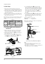
4) As rotating Disk S Reel
Œ
clockwise and the
region of adjusting in the Main Base (in shape of
slit) clockwise or counterclockwise after inserting
screw driver in the slit on Main Base. Adjust the
left end edge of Lever Tension Ass’y
ˇ
to 1.3
+1.5/-0.5mm from the location of mark in the
Main Base.
5) As rotating Disk S Reel
Œ
, double-check the loca-
tion of the left end edge of Lever Tension Ass’y
and the quanity of crossing from mark on Main
Base. (+1.0/-0.5mm)
Counterclockwise : Torque UP
Clockwise
: Torque DOWN
Back Tension should be 56 ± 15g.cm at inspecting it
with Back Tension Meter.
1.0mm
0.5mm
ˇ
LEVER TENSION ASS'Y
Œ
DISK S REEL
´
ADJUSTING
ADJUSTING SLIT
1.3
Fig. 5-16 Tension Pole and Back Tension Adjustment
5-2-4 Location adjustment and Confirmation of
Tension Post
1) Remove the holder cassette ass’y and then push
the lever FL Arm-R to the direction of loading.
2) Push the lever tension drive
Œ
in the direction of
arrow. (See Fig. 5-14)
3) Turn the gear worm wheel
´
clockwise so that
“Timing Point” of the slider FL drive
ˇ
and gear
FL cam
¨
can be aligned (See Fig. 5-14)
Fig. 5-14
Fig. 5-15
¨
GEAR FL CAM
´
GEAR WORM WHEEL
ˇ
SLIDER FL DRIVE
P
TIMING POINT
Œ
LEVER TENSION DRIVE
LEVER TENSION
<Table 5-1>
Note :
1) Mark on Main Base is located in about 1.3mm
from inside of bending line.
2) Be careful not to deform the region of adjusting on
Main Base up and down at adjusting.
MODE
TORQUE g/cm
GAUGE
PB
NTSC 82.5 ± 27.5
Cassette Torquemeter
PAL 79 ± 27
RPS
145 ± 30
Cassette Torquemeter
Summary of Contents for W603C
Page 20: ...Reference Information Toshiba 2 13 2 2 1 IC301 LA71072M 2 2 IC Blocks ...
Page 21: ...Reference Information 2 14 Toshiba 2 2 2 IC501 AN3662 ...
Page 22: ...Reference Information Toshiba 2 15 2 2 3 IC601 MN101D02X ...
Page 23: ...Reference Information 2 16 Toshiba MEMO ...
Page 25: ...Product Specifications 3 2 Toshiba MEMO ...
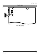
Page 56: ...Alignment and Adjustment Toshiba 5 11 Fig 5 21 Main PCB Top View VR501 Location for VR501 ...
Page 57: ...5 12 Toshiba Alignment and Adjustment MEMO ...
Page 59: ...Exploded View 6 2 Toshiba 6 1 Packing Assembly A702 A701 A702 Y101 Y102 UT01 ...
Page 63: ...Exploded View 6 6 Toshiba MEMO ...
Page 73: ...Replacement Parts List 7 10 Toshiba MEMO ...
Page 74: ...Toshiba 8 1 8 Block Diagram ...
Page 75: ...Block Diagram 8 2 Toshiba MEMO ...
Page 76: ...Toshiba 9 1 9 PCB Diagrams 9 2 9 3 9 3 9 3 9 1 Main 9 2 VFD 9 3 Jack 9 4 Key ...
Page 77: ...PCB Diagrams 9 2 Toshiba 9 1 Main ...
Page 78: ...PCB Diagrams Toshiba 9 3 9 2 VFD 9 3 Jack 9 4 Key ...
Page 79: ...PCB Diagrams 9 4 Toshiba MEMO ...
Page 82: ...Schematic Diagrams Toshiba 10 3 10 1 S M P S Power ...
Page 83: ...Schematic Diagrams 10 4 Toshiba IC601 VFD 10 2 Logic ...
Page 85: ...Schematic Diagrams 10 6 Toshiba 10 3 A V ...
Page 87: ...Schematic Diagrams 10 8 Toshiba 10 4 Hi Fi MTS ...
Page 89: ...Schematic Diagrams 10 10 Toshiba 10 5 TM Block Input Ouput ...
Page 90: ...Schematic Diagrams Toshiba 10 11 10 6 VFD ...
Page 91: ...Schematic Diagrams 10 12 Toshiba 10 7 Remote Control ...

